Continue to Site

Welcome to our site!

Electro Tech is an online community (with over 170,000 members) who enjoy talking about and building electronic circuits, projects and gadgets. To participate you need to register. Registration is free. Click here to register now.

  • Welcome to our site! Electro Tech is an online community (with over 170,000 members) who enjoy talking about and building electronic circuits, projects and gadgets. To participate you need to register. Registration is free. Click here to register now.

need help with flyback transformer

Status
Not open for further replies.
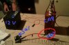
just finished working on this need to know if its connected ok..

thanks
lev77

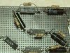
Hi, lev77. Overall this looks pretty good. Now that I think about it, though, you may want another resistor across the first diode as well. I didn't really think about that before....
You also need to make sure all your diodes are in the right way. If you have one of them backwards, you risk the rest of your diodes, your resistors, and your output. Make sure they are all connected facing the correct direction.
 
hi DerStrom
i will add another one. all the rest is as u told me they all face right way..
the IN and OUT r they on right direction? IN (-) the one with the line yes..
 
hi DerStrom
i will add another one. all the rest is as u told me they all face right way..
the IN and OUT r they on right direction? IN (-) the one with the line yes..

In order to tell which end is the cathode and which is the anode, you will have to look at the diode datasheets that you can easily find on google. I'm not sure if I understand quite what you are saying, but IN should be the "back" of the diode (furthest from the band). Here's a rough diagram:

IN ----l>|----OUT (band is on the right).

Does this make sense?
 
Last edited:
this is a close up one just check if its all good
thanks
lev 77
 

Attachments

  • zz.jpg
    zz.jpg
    1.4 MB · Views: 337
this is a close up one just check if its all good
thanks
lev 77

Okay, the diodes are all facing the same direction, but IN should be at the "back" of the diode (see my previous post). You just have your "IN" and "OUT" backwards.
 
ohh ok ill change them thanks..
other ways all good ye..

Yes, it appears so. All you have to do is make the change that I have posted below:

Rectifier.jpg
 
cool cool thanks mate for ur help
Wednesday ill tray it. will see how i go.. ill let u know...
lev 77
 
cool cool thanks mate for ur help
Wednesday ill tray it. will see how i go.. ill let u know...
lev 77

Great. You do that :)
 
after looking at the pics, let me give you a hint about soldering for high voltage. it's a bit different than low voltage soldering. high voltage soldering requires "blob" soldering. sharp points and angles are a no-no. with round blobs, air bubbles, rough spots and inclusions are also a no-no. the idea is to minimize corona discharge from bleeding energy from the circuit
 
I haven't tried to use a TV flyback in an automobile ignition circuit. I don't know if the rectifier will diminish the output voltage, or cause unpredictable results. Have you tried the website address printed on the label?
 
No luck :(
it didnt work.. with the rectifier it didnt charge the cap at all. the was no sparks coming out of it. with out of it the was more sparks from car coil then with it....
ill try to get proper rectifier this time.
thanks all for u help.. :):)
lev77
 
No luck :(
it didnt work.. with the rectifier it didnt charge the cap at all. the was no sparks coming out of it. with out of it the was more sparks from car coil then with it....
ill try to get proper rectifier this time.
thanks all for u help.. :):)
lev77

I guess I'm not quite sure what you are expecting to happen. A photo of your entire setup would be very helpful. That way, we could see if you may have connected something wrong. Any chance of posting a picture?
 
its behind the car battery

Oh, okay. Would you happen to have a schematic of your connections? In the photo I see a bunch of wires but can't quite see where they go. Sorry about all the demands--It's just somewhat difficult to follow what you're doing :D
Der Strom
 
even with an effective driver circuit, it will take a while to charge that cap up....

what are you using to drive the coil with?
i saw the circuit you had, but that requires a pulse input (like a 2khz square wave... 2khz because that's the approximate resonant frequency for an ignition coil(i know this how???? i've driven ignition coils with amplifiers to use as a crude ionophone)) to pulse the coil continuously...
 
Last edited:
even with an effective driver circuit, it will take a while to charge that cap up....

what are you using to drive the coil with?
i saw the circuit you had, but that requires a pulse input (like a 2khz square wave... 2khz because that's the approximate resonant frequency for an ignition coil(i know this how???? i've driven ignition coils with amplifiers to use as a crude ionophone)) to pulse the coil continuously...
thats the driver im using.. so how do i get that 2khz square wave pulse input????
thanks
lev77
 
thats the driver im using.. so how do i get that 2khz square wave pulse input????
thanks
lev77

If what unclejed613 said is true (I'm not doubting you, unclejed) then you would probably want a simple 555 timer circuit. A 555 timer is able to create a square wave output from a steady DC input, and it should be easy to set one up in astable mode to produce one of 2khz. Here's the circuit for an astable 555 timer:
**broken link removed**
R1, R2, and C1 determine the output frequency. I hope this helps!
Der Strom
 
Status
Not open for further replies.

Latest threads

New Articles From Microcontroller Tips

Back
Top