Continue to Site

Welcome to our site!

Electro Tech is an online community (with over 170,000 members) who enjoy talking about and building electronic circuits, projects and gadgets. To participate you need to register. Registration is free. Click here to register now.

  • Welcome to our site! Electro Tech is an online community (with over 170,000 members) who enjoy talking about and building electronic circuits, projects and gadgets. To participate you need to register. Registration is free. Click here to register now.

need help with diagram & Design of DC Motor Controller

Status
Not open for further replies.

ns5543

New Member
Who know is this schematic design valid with below material?:confused:
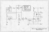
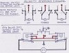
a design of dc motor controller.(reverse,stop,forward)

material
1 2N6121 transistor (NPN)
1 2N6124 transistor (PNP)
1 74LS00 (buffer)
1 74LS04 (AND)
1 74LS11 (OR)
1 74LS32 (inverters)
3 7k resistors
2 10k resistors
2 30k resistors
3 normally open pushbuttons
1 12V dc motor

schematic >>**broken link removed**

p/s: i need help if anyone know read diagram.not really understand since not electronic based.anyone can provide me better diagram especially with that ic diagram and great if can provide diagram with ic and fully function schematic as not simple schematic as pic..really hope cause it my final year project..anyone...i just grab it from **broken link removed** confuse with 74ls00 ic and lm741 in that schematic.are it related since no list of lm741 ic...if anyone can help provide me with fully function schematic diagram plus with power source input and output and other that make i can easy understand to make my project run successfully i'm really2 glad..thanks you a lot..
 
I think it would be a better idea to use a full H-bridge. Check out TEXAS INSTRUMENTS.

They have low and high power H-bridges, e.g. L293D (4.5-36V/1A), a quadruple half H-driver, which requires just three inputs of which one might be steady.

With the other two inputs the connected motor can be controlled CW/CCW and fast stop.

It has many advantages over the circuit you posted, since it requires only one supply voltage.

Boncuk
 
how..i am not really in electronic based so many of the electronic device i don't know it function..if can provide better diagram like below

**broken link removed**

but this diagram did not have material/electronic type device used..huhuhuhu...if someone understand and know what type/device electronic suitable to used from that diagram..can tell me?..huhhu...:confused:
 
gotta love relay logic... oy!

C1 and C2 reverse the motor. A2 and B2 turn it on. the others are lockout and such.

that diagram has every thing you need if you know how to read it- all the "A" parts on the schematic are parts of the same double pole double throw relay. same with all the Bs, Cs and Ds.

Dan
 
Motor speed controler

If you just want to control motor speed,you would be better off using a
Pulse width modulator (PWM).Use a LM324N Quad-op amp(8 pin IC)& a suitably rated Mosfet,the rest of the circuit only requires resistors & caps.and of course the usual diode.the circuit is controled by a potentiometer which adjusts the ampage via the gate of the fet & so to the drain.you will obviously need a heat sink for the Mosfet even if you are running at low amps.(I hope I've explained in the most un-technical terms that I can think of) good luck Terry
 
Last edited:
I agree with tblo163.
I designed a DC motor controller using a logic FET (N enhancement type) , PIC chip ( microcontroller), Schottky diode for connecting across motor.
Using very small amount of components (4 resistors, LED 5V reg and 2 caps)
you can get the circuit to dive motor at about 18-20Khz, have current limit detection, soft start e.c.t.
Only problem will be reversing. You could use a FET and a relay, or use 4 FETs (each has a diode in parallel to source and drain to snub back EMF) in a H bridge arrangement.
 
Shouldn't have a problem with reversing.The PWM's polarity MUST remain the same,but the motor's does not.bearing in mind that the negative to the motor is supplied by the DRAIN & not the source.Draw a diagram up,to see how this can work.
 
Motor speed controler

The PWM circuit is quite simple to build,on a piece of vero board,use a 14 pin IC Socket each side of the breaks in the rails.you can connect pins 2,12,9
&8 together,(they don't go anywhere else,the rest of the components are easily fitted,working you way to the Mosfets.You can use either 1 or 2 FETS,depending how much ampage you want to draw.I use two IRFZ48N,because I run at 30 amp continuous,you will also need a meaty heat sink and probably a fan.you can connect VR1 to opperate remotely if you wish.I've been running mine for allmost a year with no problems. I have a channel on Youtube,search for terryblount163 you will see why I need a 30amp, PWM.good luck Terry
 

Attachments

  • LM324N.pdf
    143.4 KB · Views: 412
  • PWM.jpg
    PWM.jpg
    1.1 MB · Views: 758
Hi ns5543,What exactly do you want to do with the motor? control speed,reverse it or both;Also what is the type of motor(some motors cannot be reversed)what is the voltage & current draw?Reverse polarity can be easily provided by two 5 pin relays(CO) & a reversing switch.An example of this to understand easily is a typical circuit for vehicle central locking.
 
Polarity reversing

Here's a couple of circuits to help you with your project.You will find this FORUM very usefull,just tell us what your problem is,and you will be surprised how many replies you get.We are happy to share our information with all who need it.By the way,what part of the world do you come from,I could possibly comunicate with you in your own language.good luck Terry
 

Attachments

  • POLARITY REVERSING.jpg
    POLARITY REVERSING.jpg
    3 MB · Views: 646
Status
Not open for further replies.

Latest threads

New Articles From Microcontroller Tips

Back
Top