Need to develop a circuit that will allow a PIC microcontroller to monitor the current to a auger motor for JAM detection.
The motor is 120 VAC and rated 0.5 FLA with a peak lock rotor current of 2.5A and a jam trip point of 1 A. I need a circuit to convert the AC amps to DC Volt (0- 5 VDC) for the pic input pin and A/d converter.
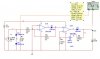
Found this application circuit at the CR micro site. https://www.crmagnetics.com/pdf/ancrct-4.pdf
CR Magnetics sent me thier burden test for the https://www.crmagnetics.com/8400.pdf. Indicates that the secondary voltage needs to be maintained less than 2V to prevent saturation.
I need to determine the values of the resistors along with teh final reistor and capacitor to get a 0-5V DC signal as the current in the primary to the CT goes from 0 to 2.5 A.
The motor is 120 VAC and rated 0.5 FLA with a peak lock rotor current of 2.5A and a jam trip point of 1 A. I need a circuit to convert the AC amps to DC Volt (0- 5 VDC) for the pic input pin and A/d converter.
Found this application circuit at the CR micro site. https://www.crmagnetics.com/pdf/ancrct-4.pdf
CR Magnetics sent me thier burden test for the https://www.crmagnetics.com/8400.pdf. Indicates that the secondary voltage needs to be maintained less than 2V to prevent saturation.
I need to determine the values of the resistors along with teh final reistor and capacitor to get a 0-5V DC signal as the current in the primary to the CT goes from 0 to 2.5 A.
Last edited: