Continue to Site

Welcome to our site!

Electro Tech is an online community (with over 170,000 members) who enjoy talking about and building electronic circuits, projects and gadgets. To participate you need to register. Registration is free. Click here to register now.

  • Welcome to our site! Electro Tech is an online community (with over 170,000 members) who enjoy talking about and building electronic circuits, projects and gadgets. To participate you need to register. Registration is free. Click here to register now.

Need help with an LED setup

Status
Not open for further replies.

jeremiahjw

New Member
Hey everyone! New user here, and not that experienced with electronics (as far as putting them together).

I'm trying to setup the lighting for a prop I built (a replica of the gun from Portal). I will have a sequence of 11 orange LEDs and 11 blue LEDs with a switch to go from one to another. What I am wondering is if I need to have resistors with that many LEDs. I saw this project where the guy had a similar number of LEDs in sequence, but he didn't use a resistor. Welcome to Slothfurnace.com... Tasty!

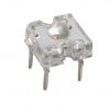
Here are the LEDs I will be using.
**broken link removed**
Forward Voltage: 3.0-3.6v
Current: 20-30mA

**broken link removed**
Forward Voltage: 1.8-2.4v
Current: 20-30mA

Here is how I would have to seperate them. I will be lighting up different sequences of the gun.

**broken link removed**

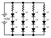
I assume I will have to set them up somewhat like this.

**broken link removed**

I don't know what voltage I need, or what kind of resistor I should use.
 
While the author (designer) in this link you provided demonstrates some machining skills with the lathe his electrical/electronic skills with LEDs leaves quite a bit to be desired. You never parallel a pile of LEDs the way he went about it. Really a bad practice.

Now as to the LEDs you have chosen for your project:

5mm Piranha LED Blue Ultra Bright 10,000 mcd
Forward Voltage: 3.0-3.6v
Current: 20-30mA

5mm Piranha LED Orange Ultra Bright 8,000 mcd
Forward Voltage: 1.8-2.4v
Current: 20-30mA

The Blue LEDs you likely want to run with a Vf (forward voltage) of about 3.3 volts and an If (forward current) of about 25 mA. The Orange LEDs at about Vf = 2.1 volts and If = 25 mA to assure a nice long life. I would experiment with a few to get the brightness good but not toasting your LEDs.

How all of this gets configured will be a function of the battery combination you choose to use. Also, if you could better explain your drawing it would help. You want a dozen orange on at one time and switched. Then you want a dozen blue on at one time that can also be switched? So either 12 orange or 12 blue on at any given time?

Ron
 
Well, if 'twere me, I'd probably do something like this:

**broken link removed**

I've divided the LEDs into series strings of 3 since you are using ~3-volt diodes and a 9-volt power source (6 AA cells), so you'd probably end up with an "extra" LED (12 instead of 11). The resistor is to limit the current--you only need one, not multiples as you indicated--and can be sized by using your formulas--you know, R=E/I and all that. (I haven't bothered to do this, but I'm sure someone could come along and do this for you if you can't.) You'll also have to make it big enough (power-wise) to handle the power it'll dissipate (I'm going to guess you'll need a 1/2 or 1 watt resistor).

You'd need slightly different values of resistors between the two colors, since they operate on slightly different voltages, but the difference may turn out to be too small to worry about. Again, someone needs to come along and plug in some values here.

(Hey, you don't want me to do everything for you, do you?)

[EDIT] Whoops, read your diagram wrong: you have your two AA packs in parallel, so you only have 4.5 volts to play with. You could, however, put them in series to get 9 volts, or use a 9-volt battery. Lots of ways to skin this cat ...
 
Last edited:
You never parallel a pile of LEDs the way he went about it. Really a bad practice.

You know, I've seen you write this before here, but I still don't know why. Why would this be a bad practice?

Sure, there will be some minor variations between diodes even of the same type. But in a parallel string, each LED can draw whatever current it needs without affecting its neighbors, and the overall current-limiting resistor should still limit overall current for the string to a safe level, right? So far as voltage goes, there may again be some minor differences between forward voltage drops among LED brothers/sisters, but again, I don't see why this would be a show stopper.

In fact, by putting them in series, aren't you in more danger of overdriving the "weaker" diodes with excessive current from the "stronger" ones?

Or am I missing something really obvious here?


OK, I always recommend against placing LEDs directly in parallel with each other because if I suggest otherwise AudioGuru will come along and beat me up really bad. :)

Seriously, I just don't see it as a good practice, especially with as many that were seen in the first link the OP posted. Will it really, really mater and seriously bad things happen? Likely not. There are countless circuits out there on the web with parallel configurations of LEDs. My thinking on the subject runs with this link and how they cover the subject. If I use a pair of LEDs in a circuit in parallel, each will have its own current limiting resistor. I do that rather than parallel two or more LEDs, multiply the current and use a single resistor based on I total. If we look at the LEDs posted as to voltage and current I don't see where a tenth or two of a volt or a mA or two will matter as long as we work in about the middle of the ranges. I guess with me it is just a matter of practice with opinion tossed in. :)

Incidentally, the link as to LED configurations is a good read.

Ron
 
OK, I always recommend against placing LEDs directly in parallel with each other because if I suggest otherwise AudioGuru will come along and beat me up really bad. :)
Cheap Chinese flashlights (flameless torches in the UK and down under) have many LEDs directly in parallel and some of them survive for an hour or more. Maybe they test and group similar LEDs so that last as long as an hour. Not recommended if you want the LEDs to last long.

There are countless circuits out there on the web with parallel configurations of LEDs.
They are Instructables that are written by nerds who know nothing about electronics.
 
I work for one of those Chinese Flashlight companies. We do have LEDs in parallel. The LEDs are sorted into 10 groups. Only LEDs with the same on voltage are used together. Randomly paralleling LEDs will (could) cause the current to be 2:1 different.
 
Cheap Chinese flashlights (flameless torches in the UK and down under) have many LEDs directly in parallel and some of them survive for an hour or more. Maybe they test and group similar LEDs so that last as long as an hour. Not recommended if you want the LEDs to last long.

BS. Pure and simple.

All of those multi-LED flashlights have strings of diodes in series/parallel. Most of them last a long time, certainly more than an hour. Your tales of terror about using LEDs in parallel can be safely ignored.
 
Last edited:
BS. Pure and simple.

All of those multi-LED flashlights have strings of diodes in series/parallel. Most of them last a long time, certainly more than an hour. Your tales of terror about using LEDs in parallel can be safely ignored.
See the previous post from a guy who works for one of those Chinese Flashlight companies. He says almost exactly what I said.
Do hobbiests test and sort LEDs into 10 groups of forward voltages?
 
Ok, I replied yesterday but the mods haven't approved my post, so I'm re-posting.

Also, if you could better explain your drawing it would help. You want a dozen orange on at one time and switched. Then you want a dozen blue on at one time that can also be switched? So either 12 orange or 12 blue on at any given time?

Yes, 11 (or 12) orange LEDs on, or 11 (or 12) blue LEDs on, but not both at the same time.

I've divided the LEDs into series strings of 3 since you are using ~3-volt diodes and a 9-volt power source (6 AA cells), so you'd probably end up with an "extra" LED (12 instead of 11). The resistor is to limit the current--you only need one, not multiples as you indicated

I'm not that good at reading electrical drawings, so I've "translated it" into noob drawings. Is this what you are talking about?

**broken link removed**
 
Last edited:
I'm not that good at reading electrical drawings, so I've "translated it" into noob drawings.
Your "noob" drawing shows ladybugs with 4 legs. Our schematics show light-emitting-diodes that have an anode and a cathode (2 pins).

You show your ladybugs connected in parallel. We connect LEDs in series, not in parallel.

You show a 3V battery, not a 9V battery.
 
Your "noob" drawing shows ladybugs with 4 legs. Our schematics show light-emitting-diodes that have an anode and a cathode (2 pins).

Yeah, the lights are square and have 4 pins, but I'll have just two in the rest of the drawings.

Ok, so I redrew it with the total number of lights for one side. Is this how it would be wired?

**broken link removed**
 
Your new drawing has two-legged lady bugs but no LEDs.
LEDs have an anode (the + wire) and a cathode (the - wire) that are always shown on a schematic but are not shown on your sketch. If the anode and cathode are connected backwards then the LEDs will not light and might be damaged.

Each string of 3 LEDs in series needs to have its own current-limiting resistor. The "3.3V" LEDs might actually be 3.6V each so a 9V battery is not enough. use a 12V battery.

Carbonzit likes to gamble. His battery voltage is too low and he does not have enough resistors.

Here is a Philips Luxeon Superflux LED that has 4 pins. Here is a schematic showing your LEDs, resistors and a 12V battery.
 

Attachments

  • Luxeon SuperFlux LED.jpg
    Luxeon SuperFlux LED.jpg
    4.8 KB · Views: 303
  • LEDs again.PNG
    LEDs again.PNG
    4.1 KB · Views: 312
Your new drawing has two-legged lady bugs but no LEDs.
LEDs have an anode (the + wire) and a cathode (the - wire) that are always shown on a schematic but are not shown on your sketch. If the anode and cathode are connected backwards then the LEDs will not light and might be damaged.

The idea is that one side was positive, and the other negative. The poles might not be correct, I'm just trying to figure out the positioning of everything.

So aside from that, voltage, and the resistor, is it setup right?
 
The idea is that one side was positive, and the other negative. The poles might not be correct, I'm just trying to figure out the positioning of everything.

So aside from that, voltage, and the resistor, is it setup right?

Yeah, you want a resistor for each series string of LEDs as AG drew it and you need enough voltage as AG drew it. Make those changes and you are there.

Ron
 
If you look at AG's schematic the Anodes of the LEDs are (+) and the cathodes are (-). Three LEDs in series and each series string has a current limiting resistor. The resistors can be placed on either side of the LED strings. The power supply (battery) is 12 volts.

Ron
 
Awesome! Which side of the LED in the diagram is positive?
An LED is a diode so it uses the symbol of a diode with arrows representing light beams.
All diodes have an anode (+) and a cathode (-). When we see the symbol of a diode then we know which wire is which.
I copied this one from the first article about LED in Google.
 

Attachments

  • LED again.PNG
    LED again.PNG
    1.5 KB · Views: 264
Polarity

Pins 1 & 2 are the anode. They go to the positive side of the battery.
 
Ok, I think I'm almost there.

12v battery - check
24 leds (12 for each color) - check
8 resistors - check

Since I'm using one resistor per 3 LEDs, how would I put that into the array wizzard? **broken link removed**

What number do I put in for total LEDS? 12 or 24?

For diode forward voltage and current, I have two figures on the website, 3.0-3.6v/1.8-2.4v and 20-30mA/20-30mA, which figure do I use?
 
Status
Not open for further replies.

Latest threads

New Articles From Microcontroller Tips

Back
Top