Continue to Site

Welcome to our site!

Electro Tech is an online community (with over 170,000 members) who enjoy talking about and building electronic circuits, projects and gadgets. To participate you need to register. Registration is free. Click here to register now.

  • Welcome to our site! Electro Tech is an online community (with over 170,000 members) who enjoy talking about and building electronic circuits, projects and gadgets. To participate you need to register. Registration is free. Click here to register now.

Need help with a simple LED grow light circuit

Status
Not open for further replies.

dogfight14

New Member
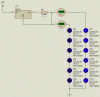
Hi everyone, I am currently working on an LED grow light which consists of 20 1W blue LEDs, 20 1W red LEDs, and a 10W soft white LED (shown in yellow on my diagram).

I have mocked up what I think the circuit will roughly look like, but need a bit of help with the details of it...

**broken link removed**

The LED specs are as follows:

10W WHITE LED:
* Reverse Voltage:5.0 V
* DC Forward Voltage: Typical: 10 V Max: 12V
* DC Forward Current: Typical: 900mA Max: 1050mA

1W BLUE & RED LED:
* Reverse Voltage:5.0 V
* DC Forward Voltage: Typical: 2.2 V Max: 2.4V
* DC Forward Current:300mA

If anyone can help me work out the following, there will be a donation from the project's budget ;)

  • Whether it will work; and if not, what I need to do to it
  • The resistance of the resistors
  • The max resistance of the variable resistor
  • Any additional changes which would benefit it

Please note: I put them into the 5 parallel lines of 4 LEDs just because I thought this might be appropriate, not for any inparticular reason :p

Look forward to hearing what people have to say, thanks for reading,

Col
 
Hi Col,

welcome to the forum.

One string of four LEDs requires 300mA, which are 10 strings total, requiring 12V at 3A, not counted the white LED at approximately 1A.

You must use a current limiting resistor in each string because of different LED forward voltage and currents resulting using just one current limiting resistor for five strings (blue and red each).

Dimming the LEDs with a single pot is not possible for the reasons already mentioned above. Carbon film pots cannot be used to dim those relatively high current LEDS, even if using a separate pot in each string. At a current of 300mA and 1V of voltage it has to drop the power dissipation is 0.3W - which they can't handle. (0.25W max)

I suggest to use constant current sources as offered by many LED shops and select one suiting your needs best.

Boncuk
 
Thanks for the reply, you have some good information there for me!

I understand each sentence you write, but overall on a project level, I am even more confused! =P I thought I could blag my way through this circuit using what I remember from GCSE systems&control and a little bit of research, but its turning out than it is much more complicated that I had imagined.

I already have the following parts:

  • 1x 10W White LED
  • 20x 1W Red LED
  • 20x 1W BLue LED
  • Various colours of wire
  • 12v DC Power Supply
  • Soldering iron, solder, etc that sort of thing (all the tools)

So what else do I need to buy to make this concept work?

& How will it all go together?

Thanks, Col.
 
Last edited:
Hi Col,

you certainly must have have each colour dimmable which means usage of a variable current source.

I studied several offers of dimmable LED driver circuits and for your case I guess the price will be astronomically high. Additionally I didn't find any rated 300mA output.

A simple solution would be dimming one set (five strings per four LEDs) of LEDs with one voltage/current regulator. This means the LEDs should be off the same production lot (batch) with little difference in forward voltage.

The L200 is a voltage/current regulator with a maximum output current of 2A, suiting your needs for 1.5A (one set of LEDs) perfectly. Since the current sensing voltage of it is (typically) 0.45V a low wattage potentiometer can be used to control the output current, hence the brightness of the LEDs.

So what you'll finally need besides a power supply and wires is a PCB with the regulators and potentiometers to make control easy.

The minimum required current for your entire LED project is roughly 4A (2X1.5A red and blue + 1A white). With a safety margin of 25% the power supply should be able to handle 5A without overheating.

If you like that solution I'll be glad to design the schematic and PCB layout for you.

Boncuk
 
Last edited:
Cheers man you clearly know what you are talking about.. =D

How much do you think all this would cost me?

If you could do the design that would be so helpful to me, and I really would appriciate it.

The only thing I dont understand in your previous post is the L200 regulator and where this would go/what this would do.

I cant thank you enough for this help

Col =]
 
Hi Col,

I've simulated a circuit with two strings of LEDs (5 in series). If only one LED has a different forward voltage (D3=VF2.2V) from the others the forward current drops considerably for this chain, hence dimming the entire string. (see attached simulation and the values next to the LEDs and the connected am-meter)

So the L200 will be wasted, since each string requires its own current regulator, which could be done using LM317T for 25Cents each. (The L200 is about US$2)

Using discrete voltage regulators wired as constant current regulator this would mean to use 11 regulators total (5 for red, 5 for blue and 1 for white). The next question would arise how to dim 5 strings using one knob.

I will check the possibilities to use an integrated LED control circuit, which I know are available even with PWM-control to dim the LEDs.

Regards

Boncuk
 

Attachments

  • LED-UF.gif
    LED-UF.gif
    9.2 KB · Views: 1,334
Status
Not open for further replies.

New Articles From Microcontroller Tips

Back
Top