Aidis
New Member
https://www.epanorama.net/circuits/parallel_output.html
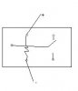
(Were it sais , new safer design for the relay)
This is the circuit i need to make , am i doing ok in the attatched image?
Thanks!
(Were it sais , new safer design for the relay)
This is the circuit i need to make , am i doing ok in the attatched image?
Thanks!