Continue to Site

Welcome to our site!

Electro Tech is an online community (with over 170,000 members) who enjoy talking about and building electronic circuits, projects and gadgets. To participate you need to register. Registration is free. Click here to register now.

  • Welcome to our site! Electro Tech is an online community (with over 170,000 members) who enjoy talking about and building electronic circuits, projects and gadgets. To participate you need to register. Registration is free. Click here to register now.

Need help with 555 PWM with current limiter

Status
Not open for further replies.

Superman--

New Member
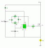
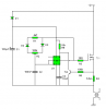
Okay here is the basic issue. (image of current design on bottom)
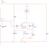
I have 555 timer PWM multichannel board and I blow MOSFETs like crazy.
So I have imposed a Voltage limiter for the PWM but still blow the MOSFETs.

So the I went to redesign that .
I have new MOSFETs that are 12v 75A each. With single current flow configuration.

So does anyone see any flaws with this design?

Also each MOSFET will run around 40A-60A draw continuance.
And so does anyone have an idea on how to limit the current to the load.
Just so I do not go over 50A. Any input would be appreciated.
work..jpg
By the way the program I am using says that this will work but cuts out after 15 seconds. It's driving me nuts.
Thanks again in advance.
 
What frequency are you using?

How about using the circuit attached?

It's much simpler, just connect it in series with the load.
 

Attachments

  • Two wire 7555 dimmer.GIF
    Two wire 7555 dimmer.GIF
    4.8 KB · Views: 1,156
hi,
Whats is the Load.?

Also do you have a large capacitor on the +14V regulated supply to the load.?
I assume the PIC drive is 5V.?
 
I forgot about the current limiter.

There's probably a way to limit the current with my dimmer circuit a current sense resistor and comparator with an RC circuit shorting the reset pin will probably work but I've not done any calculations or even designed it yet.

How do you know about the PIC Eric, don't tell me there's another thread somewhere I don't know about?:rolleyes:
 
What frequency are you using?

How about using the circuit attached?

It's much simpler, just connect it in series with the load.

It is a variable frequency, from your diagram C2 I have a variable capacitor.

thanks for the tip I will give it a shot.
 
hi,
Whats is the Load.?

Also do you have a large capacitor on the +14V regulated supply to the load.?
I assume the PIC drive is 5V.?

The load is up to 1800 watts total. That is 12v at 150A.
That is why I would like to limit the load some how.
I do not want to burn it out.
I do have a 25V 12,000 uF capacitor which I unfortunately clipped off the image.
 
It is a variable frequency, from your diagram C2 I have a variable capacitor.
Why do you want to vary the frequency?

Again, what frequency are you using?

My circuit is fixed frequency, variable duty cycle which is what you need to dim a lamp or control the speed of a motor.

Good luck finding a 100nF variable capacitor.
 
Why do you want to vary the frequency?

Again, what frequency are you using?

My circuit is fixed frequency, variable duty cycle which is what you need to dim a lamp or control the speed of a motor.

Good luck finding a 100nF variable capacitor.

This is for an experiment so I need to experiment.
I understand that just changing the duty cycle will make it work faster or harder, but I don't know in my experiment where the duty cycle is or the frequency will make it work best or not.

It's not exactly a variable capacitor I have 10 capacitors connected to a 10 pin dip switch. So I can change the pulse width and frequency.


ALL OF WHICH WORKS FINE.

But if you really want to know this is connected to HV transformer.
OR Induction coil, and that is why I need to change so many variables.

I just keep blowing MOSFETS and want to limit the current.
I built it with 2N3055 and they suck.
So that is why I want to put two 75A MOSFETs so I don't blow it out and can spread the heat out a little.
That is why I want to limit the current to 100A so I don't over load anything.
Please that is what I need help with.
 
Last edited:
Good you've learnt that the 2N3055 isn't a very good choice.

You need a snubber network or a diode to suppress the high voltage transient created when the coil is turned off, otherwise the MOSFETs will be killed.

The current is probably exceeding 100A because the transformer's core is saturating.

There will be a maximum amount of time you can have the transformer connected to the power supply before the core saturates; this will be determined by the: voltage, saturation current, the inductance of the primary; the latter will depend on the load connected to the secondary.

Ideally the duty cycle and frequency should depend on the load, here's how I'd do it:

Turn on the transistor.

When the current reaches a certain threshold turn the transistor off.

Wait for a pre-determined amount of time before turning the transistor back on.

A comparator and a MOSFET driver could be used to accomplish the above.

For maximum efficiency the turn-off threshold current should be less than the saturation current.
 
I know it sounds weird but it's pretty similar to a high current LED driver, without the LED: I suggest you read the following thread:
https://www.electro-tech-online.com/threads/high-power-led-controller.95832/

Then you'll hopefully understand how a comparator can be used to make a self-oscillating driver which can be used to switch your coil and I can help you with putting together a circuit, unless you've figured out how to do it your self.
 
That will limit the current but when it does the power dissipation will be huge.

If the drains of Q1 and Q2 are shorted to +V with the gate voltages taken high. The voltage across R4 will rise until Q3 shorts the gates of Q1 and Q2 to 0V. An equilibrium will soon establish with about 3V across R4, and the 555 timer's output being short circuit to 0V. The whole think will cook pretty quickly because the power dissipation will be high.

I take it, the LED symbolises the coil?

Don't forget that the load is inductive which is important.

You don't want an equilibrium to form, you need oscillation.

Here's an idea.

When the votlage between Tr2's base and emitter exceeds about 0.6V it will turn on which will pull 555's pin 4 down resetting the timer causing the output to go low, turning off Tr1. The output will go high again after a period determined by C2, R1 and R2's setting.

R4 will need to be a pretty large power resistor rated to 65W. It's possible to reduce the size of the resistor but you'll need to replace Tr2 with a use a comparator and a voltage reference.

I noticed you're using a NE555 rather than the 7555 so I added a capacitor to pin 5 as is recommended by the datasheet but it doesn't make any difference to the operation of the circuit.

I haven't simulated of tested this circuit but it should work.
 

Attachments

  • Coil driver I li&#109.PNG
    Coil driver I li&#109.PNG
    2.2 KB · Views: 587
The first circuit probably isn't powerful enough.

The second circuit lacks emitter resistors which are required to ensure the current is shared equally between the transistors.

They all use the 2N3055 which the original poster has tried and wasn't satisfied with.
 
Status
Not open for further replies.

Latest threads

Back
Top