Continue to Site

Welcome to our site!

Electro Tech is an online community (with over 170,000 members) who enjoy talking about and building electronic circuits, projects and gadgets. To participate you need to register. Registration is free. Click here to register now.

  • Welcome to our site! Electro Tech is an online community (with over 170,000 members) who enjoy talking about and building electronic circuits, projects and gadgets. To participate you need to register. Registration is free. Click here to register now.

Need help to build a time delay circuit to switch off/on a relay

Status
Not open for further replies.

milkoni

Member
Hi,
I need help to build a time delay circuit to switch off/on a relay. I know that this it's possible with regular time delay circuit and another relay, but I don't want to use this way.
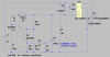
See attached file for details.

Thanks in advance!

Best regards,
Milkoni
 

Attachments

  • time_delay_relay_switch.png
    time_delay_relay_switch.png
    42.2 KB · Views: 266
I think something like this should do what you want if it is different enough from a "normal timer to meet your requiremnts.

4060timer.png


You may have to alter the relay driver circuit to suit the current taken by your relay coil.

Les.
 
Thanks Les,
very useful circuit - I'm going to try it.
By the way, I've decided to to separate my request in two parts. First - time delay part and Second - driving a relay part.
I found a proper circuit for first part on the net. For second - I have circuit from my old project.
Then I've decided to try to combine them both.
In first attached file is the circuit and simulation of the second part - driving a relay. When the input is low, the relay is ON. When the input is high, the relay is OFF.
In second file is just circuit of time delay part. I can't do the simulation, because I haven't a proper spice model for a used triac.
 

Attachments

  • relay_driving.png
    relay_driving.png
    34.1 KB · Views: 151
  • time_delay.png
    time_delay.png
    40.8 KB · Views: 178
Last edited:
Here is my hack at it. I am assuming that S2 comes from a contact closure. The circuit has more-or-less symmetrical delays on both rising and falling edges of S2. Note I(L1) relative to V(s2) in the plots.

The delay is ≈R1*C1, so you could use a 1meg pot for R1 or change C1 as needed. If you want asymmetric delays (separately adjustable) , then you can replace R1 with two pots and steering diodes. M1 is old-school NMOS like a IRF510 which has a Vth of ~4V (not logic-level like more modern ones). The relay is almost any 12Vdc relay, even the 85Ω automotive sugar-cube type would work.

rl.png


I have attached the LTSpice file so you can play with it...
 

Attachments

  • RelayTimer.asc
    3 KB · Views: 126
A Triac is not a good part for driving a 12 Vdc relay. It has an excessive forward voltage drop that is only 1% of the AC powerline but maybe 20% of your relay power source. Plus - it latches itself on until its current goes to zero.

Also, for clarity, is the relay on for 40 seconds when power is applied, or off?

ak
 
It occurred to me that you also use a 555: Similar in concept to what I posted as #4.

rl5.png
 

Attachments

  • RelayTimer555.asc
    2.5 KB · Views: 107
Hi milkoni,
In post #1 you say that you want the relay to be turned off 40 seconds after the trigger signal is at +12 volts and foor it to turn back on as soon as the trigger signal goes low. The triac timer will turn the relay on after the delay and turm it off when the power is removed. (Which is the opposite of what you requested.) You may be able to get round this by swapping over the NC and NO contacts on the relay. For my circuit to work that way would require two less transistors.

Les.
 
Les's post made me look again, and I agree that I had made it too complicated. Here is a simplified version that delays on make, and instantly releases the relay on break.

rl5a.png
 

Attachments

  • RelayTimer555a.asc
    2.4 KB · Views: 118
Hi Mike,
My understanding from the attachement in post #1 was he wanted the relay coil to be de energised 40 seconds after the control signal went to 12 volts and that he wanted it energised again as soon as the control signal went low. I don't see why he could not use it the way you have designed it just by swapping the NO amd NC contacts on the relay.

Les.

Or with this trivial modification:

rl5b.png
 

Attachments

  • RelayTimer555b.asc
    2.4 KB · Views: 120
Thank you all boys!
Excuse me please for my bad explanation of my idea.
Let me try to explain better.
The purpose of this circuit is to cut of the power to fuel pump when the LPG ECU switch to LPG. When it switch back to petrol - to power again the fuel pump.
The time delay for cutting off the fuel pump is necessary, because the signal for switching from LPG ECU comes 5 to 40 seconds earlier before switching petrol injectors OFF and LPG injectors ON (this time is adjustable by software of LPG system).
Hi milkoni,
In post #1 you say that you want the relay to be turned off 40 seconds after the trigger signal is at +12 volts and foor it to turn back on as soon as the trigger signal goes low. The triac timer will turn the relay on after the delay and turm it off when the power is removed. (Which is the opposite of what you requested.) You may be able to get round this by swapping over the NC and NO contacts on the relay. For my circuit to work that way would require two less transistors.

Les.
Yes Les, I want the relay to be turned off 40 seconds after the trigger signal is at +12 volts and to turn it back on as soon as the trigger signal goes low. I gave the circuit with a triac just as example.
And now I think that is better to tun on a relay on 40 seconds after the trigger signal is at +12 volts and to turn it back off as soon as the trigger signal goes low. As you say "by swapping over the NC and NO contacts on the relay".
In that way I decided to use the Mike's circuit from post#8.
The circuit from Mike's post #10 is very useful too...

I have all necessary elements to test it on breadboard.
 
Last edited:
Here is my hack at it. I am assuming that S2 comes from a contact closure. The circuit has more-or-less symmetrical delays on both rising and falling edges of S2. Note I(L1) relative to V(s2) in the plots.

The delay is ≈R1*C1, so you could use a 1meg pot for R1 or change C1 as needed. If you want asymmetric delays (separately adjustable) , then you can replace R1 with two pots and steering diodes. M1 is old-school NMOS like a IRF510 which has a Vth of ~4V (not logic-level like more modern ones). The relay is almost any 12Vdc relay, even the 85Ω automotive sugar-cube type would work.

View attachment 105094

I have attached the LTSpice file so you can play with it...
Mike, I like this circuit too, but there is some delay after the signal +12V is off.
 
Mike, I like this circuit too, but there is some delay after the signal +12V is off.
Yes, that was the error in my understanding of your requirements that Les pointed out to me, which I corrected in post #10.
 
Yes, that was the error in my understanding of your requirements that Les pointed out to me, which I corrected in post #10.
Yes Mike,
that circuit is perfect!!! I tested it on a breadboard - working pretty good.
But I decided to use this from post #8.
And like always - simple and effective!:)
Thank you very much!
 

Attachments

  • time_delay_cut_off_fuel_pump_circuit.png
    time_delay_cut_off_fuel_pump_circuit.png
    47.3 KB · Views: 138
  • time_delay_cut_off_fuel_pump_circuit.asc
    3.3 KB · Views: 107
Last edited:
Status
Not open for further replies.

Latest threads

New Articles From Microcontroller Tips

Back
Top