Continue to Site

Welcome to our site!

Electro Tech is an online community (with over 170,000 members) who enjoy talking about and building electronic circuits, projects and gadgets. To participate you need to register. Registration is free. Click here to register now.

  • Welcome to our site! Electro Tech is an online community (with over 170,000 members) who enjoy talking about and building electronic circuits, projects and gadgets. To participate you need to register. Registration is free. Click here to register now.

need help selecting the right optocouple

Status
Not open for further replies.

jbest

New Member
hello i am new here and came across the site trying to find an answer to the topic of this thread any help would be wonderfull cause this is driving me nuts

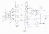
i am building a circuit the part i need help is selecting the right optocouple to be driven off a 7404 hex inverter which will then drive an scr i was looking for a 6 pin optocouple with a transistor output with no base i was going to put 12 volt in the input of scr drive side of the opto dose any one have any suggestion below is pdf of scrs i will be using
 

Attachments

  • L104.pdf
    51.2 KB · Views: 365
Have a look at the datasheet for the MOC3020/21 there should be some helpful info on interfacing to SCR's.
 
the problem is im not really an electronics person and dont know what to look for i kinda surf around and find stuff that fits what im doing and the cut and splice stuff together

but i will look at it and see

i tried cny17-3 opto it worked on the 7404 side except it dosent let enought current or volts go thru to activate the scr
 
When making something with electronic components the more you learn about the parts & research the fundamentals the easier it will be to get something working.

I have learned more from datasheets & application notes than I can poke a stick at. Most Datasheets have a brief application circuit & this is always a good starting point.
In the olden days datasheets were hard to get & often had to pay money for the book. The interweb has transformed datasheet availability enormously.

The MOC302x series of opto couplers are made for interfacing to SCR's / Triacs, for light loads & low voltage the opto output can be used directly.
-----------------

What indication do you have that it is working at the 7404 end.


From the datasheet of the CNY17-3 it has a current transfer of minimum x100 & maximum transistor current of 100mA,
so 1ma of LED input current should allow 100mA transistor output current.

From this you could place a 470 ohm resistor from the 7404 to opto which should give you about 10ma LED current in the opto, this will ensure the transistor will saturate(turn on hard).

Can you post a pic of your circuit & an explanation of what you are trying to make. Need more input - ....
 
thank you toniqau i put a 470 ohm resistor in and it worked perfectly

i really appreciate the help you saved me alot of time
 
Last edited:
toniqau i think i spoke to soon the circuit works fine with a tyn 416 scr in it but when i put in the scr i want to use in the opto dosent let enought current thru to turn on the scr

i cant use a tyn 416 it blows out in a few minutes of run time

so i still come to the point my opto isnt letting enought by what should be my next option

my circuit consist of a 555 squarewave 1000 htz to 3 divide by 10 ripple counters and then to the 7404 with 4 outputs to optos to 4 scrs i have 12volt sunk thru one gate of the 7404 thru led to ground and used the other gate to trigger the 4 gates for the optos
 
Last edited:
i attached a pic of the circuit

i also order some of the optos that tonigau recomended but could only get the nte version nte3048 the nte tech said they should work
 

Attachments

  • Picture 018.jpg
    Picture 018.jpg
    285.3 KB · Views: 238
Last edited:
i put the nte 3048 in and now their is enought current to turn on the scr

but the opto is on all the time

is their a way it can be saturated on the trigger side

i m sorry if this is dumb but i know nothing of electronics
 
Hi Jbest, sorry I don't have regular web access & some time can be days.

The output stage of the MOC302x optocouplers work differentl to a transistor output opto. The output is a low power triac & once turned on will stay on untill its is current reduced below a threshold value (same as the SCR you are using).

The MOC3020 can be activated with no LED input current under some conditions like high rise time voltage (eg: switch bounce noise) This is false triggering but usually its spurious operation.

You probably need to check that the opto input is actually turning off properly or it could be the way the opto output is conneted to your SCR.

Try disconnecting the input to the opto,
If the SCR is still on then the scr to opto circuit is the problem.
If the SCR now stays off then it would be the LED in the opto is still being supplied current ie: not turning fully off.

The datasheet for the MOC302x/ NTE3048 opto will be a good resource, read it thru even if you dont understand parts of it at first, look at the application diagram.

Best thing you can do is sketch out a circuit scan/photo & attach it but it must be clear.

The photo is not clear enough to be any help.

12volt sunk thru one gate of the 7404 thru led to ground and used the other gate to trigger the 4 gates for the optos

The 7404 IC is a 5V (4.75 to 5.25 supply) device & has a maximum of 5.5V input.

Are you switching mains full wave, maybe a triac (like dual SCR) is more appropriate.

MOCxxx App note attached for info.
An example of DC applictaion of scr attached, C10/R12 is for false trigger protection from high dV/dT transients (eg: switch on) This circuit is a Crowbar OVP for a 50V power supply.

Tonig au
 

Attachments

  • AN_3003.pdf
    73.2 KB · Views: 345
  • SCR DC.gif
    SCR DC.gif
    15.4 KB · Views: 332
thanks for the replie tonigua

i did some reading the problem i had with my orginal optocouple was it could only pass 1.5 v ?ma if i read the spec sheet right i found another version of the cny17f-3 from a different manufacture that is capible of 70 volts and 150ma in looking at the data sheet for the scr i want to trigger it had a graph that showed i needed 3.75v and 50ma to trigger am i correct in assuming this one will work

Digi-Key - 160-1320-5-ND (Lite-On Inc - CNY17F-3)


i did every thing that you recommended with checking the problem is the deffinatly the opto if i disconnect them the scr are off with the old ones in i jump both out put and it went on i put a scope to each opto input and i have squarewaves its just down to me getting the right optocouple

i read some were that 7404 have an input current to the ic of 5 volts but thru a gate you can sink or pull up to 15 volts it seems to be working for me with no problems so far
 
tonigua i drew out the exact back part of the board from the 7404 thru to the optocouple goes i simplified the drawing of the lower portion to the scr
 
tonigua i drew out the exact back part of the board from the 7404 thru to the optocouple goes i simplified the drawing of the lower portion to the scr


the pdf didnt go thru the first time

i was trying to make a burst of 4 half waves at a 1000htz
 

Attachments

  • scan0001.pdf
    235 KB · Views: 197
Last edited:
The NTE3048 should be better than the CNYxxxx opto for this application.

The opto drive side looks ok, however Please confirm value of "Positive +"
Didn't you mention this was 12V ?

The 2 optos CNYxxx & NTE3048 have different pinout pin 4 is not used on the NTE you need use pins 5 & 6.

From your sketch it shows 4 opto outputs paralleled driving 1 SCR or is this "simplified" (are there 3 other scr's) ?


Attached is a basic circuit for SCR drive from TTL logic(7404) use this as a guide for your circuit.
The circuit attached is for unsmoothed DC to allow the SCR to commutate (turn off)

Can you please detail the SCR side of your circuit, & please describe the project & what you are trying to achieve. I suspect you are switching AC in wich case you do not need the "separate supply", the SCR trigger current comes from the load supply. (see circuit attached)

It is a bit difficult to help when I do not have all the details.

Slight error in sch opto state (should read HI = on for 7404 output)
.
 

Attachments

  • Opto drive & SCR.gif
    Opto drive & SCR.gif
    52.1 KB · Views: 846
Last edited:
postive in to 7404 is 5v

their is an scr for each opto couple

i have the nte3048s in i hooked the up according to the data sheet

the circuit you showed above is exactlly the way i had it set up in the beginning and then tried to change it to 12 to fix the problem which now looks like i had the wrong optocouple

i will give your schematic a try with this optocouple and be back in a bit thank you tonigua

you are right i am trying to switch of of halfwave dc and speed it up to 1000hz
 
Last edited:
Jbest added some text to previous (after you replied)

Can you please detail the SCR side of your circuit, & please describe the project & what you are trying to achieve. I suspect you are switching AC in wich case you do not need the "separate supply", the SCR trigger current comes from the load supply. (see circuit attached)

It is a bit difficult to help when I do not have all the details.

Slight error in sch opto state (should read HI = on for 7404 output)


Where on the planet are you anyways (are you up late) or in southn hemisphere.
 
im in new york im up till about 1 am in a second i have to go a turn on the boat pumps cause it is rain here i will be back in an hour or so
 
tonigua here is a drawing of 7404 to the output of the circuit
 

Attachments

  • scan0002.pdf
    322.2 KB · Views: 197
1.
Keepi it coming, I still need more input.

I dont quite follow your DWG, You need to show everything, your power supply, loads (lamps?).
Is it rectified AC 60hz
The "20Volts" is this +20V or -20V

I cant tell which pins on the SCR are K(2) or G(3) Label them as in the datasheet.

I assume the following:
4 devices shown are the SCR's, there are only 2 connections shown, Where is the connection to the threaded stud (Anode(1))
Resistors are fitted to the opto inputs
Circuit is as viewed from the bottom.
You dont have the pin numbers shown on the opto's & it looks like connected to pins2 & 3.

I understand you are not familiar with electronics but you need to supply every detail it will help enormously.

Looks like the SCRs are not connected correctly.
Better to start with 1 only SCR, get that working then repllicate the other 3 channels.
Here is how an SCR needs to be connected:
Pin 1(A (Stud)) of the SCR should go to the positive supply, Pin 2(K) should go to your load (lamp?) & the othe side of the lamp to Negative supply.
The gate needs to be switched (via opto output & resistor) to pin 1(A) of the SCR & the SCR will now stay on untill the supply goes off (in the case of rectified AC (unsmoothed DC))


2. You should not be putting 12V anywhere near your 7404 unless there is plenty of resistance. (absolute maximum +V for a 7404 is 7V at any pin)

I am out of contact for a coupl of days so good luck, someone else should be able to help if you have enough beer to go around.

I have attached amended your drawing (its not quite same as I described above) should help you in the right direction.

ToniGau
 

Attachments

  • Scan002-Amend.jpg
    Scan002-Amend.jpg
    329 KB · Views: 240
Last edited:
tonigua here is the updated drawing it is the way i have the circuit set up as of now i see that in your version you took out the connection between each opto/scr can i ask what is the difference i will try it like in your drawing it will just take me a day or so

the circuit dose open and close just like a 60hz halfwave the thing is with it latching open till the current falls back to zero it dosent speed up it is just like having 60hz is that cause of the dual direction optocouple

the 7404 works fine with 12 volts put in to it i copyed it from another circuit i everything in my circuit works right up to the optocouple i put the scope on r1 thru r4 and have squarewave

thanks james
 

Attachments

  • scan0004.pdf
    425.5 KB · Views: 174
James,
Much clearer now, thanks for the added detail in your drawing.

The SCR's should be switching as per your drawing, however note the following points & questions.

The gate resistors value R5, 6, 7, 8 are selected to provide enough current to trigger the SCR into conduction at a specific supply voltage, with varying the voltage supply there will be a point at low supply where there will be insuficient gate current to turn on the SCR.

Are all 4 cathode(K) of the SCR's connected in parallel as shown in your drawing?, or are there 4 separate channels of +dc out. ?
If scr's are parallel then they are likely to not current share equally, at least one will take most of the load, you will need to add equalising resistors in series with each SCR K lead. There may also be some un equal turn-on turn-off time but this should be tolerable.

What is the load (S) as Resistive (lamps, heaters) & Inductive (motors, solenoids..) require slightly different gate drive requirements (see app. note)

You will not be able to achieve the waveform as you have drawn, once an SCR is conducting it will not turn off untill the half wave has gone back to near zero. This is how SCR's operate, the current flowing thru them keeps them turned on.
The "dual direction opto" is of no concern as this is a DC circuit.

You will need to use a transistor (IGBT / MOSFET) if you need to modulate the 100hz as depicted in your drawing.

Also anomoly in your detail: "typically 20-30V", elsewhere stated 0-120V.

What is your load (or loads) & how many amps.

Hope this helps,

toni
 
Status
Not open for further replies.

Latest threads

New Articles From Microcontroller Tips

Back
Top