Continue to Site

Welcome to our site!

Electro Tech is an online community (with over 170,000 members) who enjoy talking about and building electronic circuits, projects and gadgets. To participate you need to register. Registration is free. Click here to register now.

  • Welcome to our site! Electro Tech is an online community (with over 170,000 members) who enjoy talking about and building electronic circuits, projects and gadgets. To participate you need to register. Registration is free. Click here to register now.

Need help isolating a digital panel meter

Status
Not open for further replies.
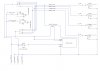
I don't know if any of you remember, but I'm attempting to build a small power supply. My supply will have a 3.5 digit panel meter that will run off of one of the 7805 voltage regulators that I plan to use as a source for my supply. I am doing this because the meter uses less than 200 mA. The meter needs to be isolated from the ground that the supply will use. To do this, I was SUGGESTED a pulse\isolation transformer: muRata 78601/16C. I've attached a sketch about how I thought this would be hooked up. So, I tested my circuit just as I have it drawn. Boy, did my 7805 GET HOT! This is WITHOUT ANY LOAD ON THE TRANSFORMER! I got 5 of these things from Newark Electronics because I ask them what I should use (I even sent them the same drawing). Now, they are telling me I need to use an AC CHOKE:

It appears you would need a common mode choke than a pulse/isolation transformer. Please check on the Sku # 98Y5771 or SKu #98Y5870 as in-stock alternative.

https://www.newark.com/schaffner/rn114-2-5-02-3m3/filter-common-mode-3-3mh-2-5a/dp/98Y5771
https://www.newark.com/schaffner/rn222-2-5-02-5m6/filter-common-mode-5-6mh-2-5a/dp/98Y5870

To return the product please fill up the form at https://www.newark.com/help-returning-a-product & send it to us. Our customer support team will help you further on this.

Thanks & Regards
Avijit Dutta
Technical Support Engineer
E: techsupport@newark.com

What am I to do?
Please advise!
 

Attachments

  • PowerSupply Switching Matrix.jpg
    PowerSupply Switching Matrix.jpg
    152.7 KB · Views: 125
A transformer winding is just a piece of wire at DC; it's just putting a direct short across the 5V supply, as you show it?

I've found the previous thread on here but cannot see any mention of that transformer or the digital meter?
Can you link to wherever you were given that info?

Why do you need to isolate the meter - it's internal to your power supply unit and reading relative to ground / 0V output anyway?
 
Why do you need to isolate the meter - it's internal to your power supply unit and reading relative to ground / 0V output anyway?
Some digital voltmeter modules don't work properly with their power supply and signal grounds connected together. I expect that's what the op has and is looking to isolate the power to the voltmeter to get around the problem.

newbieXperimenter5960, The transformer that you have is intended to be part of a DC to DC switching power supply. It would do what you need in this application, but only if you wrap quite a bit more circuitry around it first.
 
Some digital voltmeter modules don't work properly with their power supply and signal grounds connected together.

The simplest and cheapest solution to that is find another panel meter module that will work without an isolated supply; there are dozens of types and far cheaper than an isolated DC-DC converter.
 
I've got some modules from Banggood at home, intended EXACTLY for this purpose, they take a DC input and provide an isolated DC output, I bought some on the grounds they might be useful - I'll check their part number when I get home.

Otherwise, as it's a mains powered unit simply add an extra small 5V mains PSU just to feed the meter, such as these:

 
The instructions for the meter I am using say to isolate the ground to prevent ground loops.
I am using this meter because it can measure + and - voltages. I have already bought a meter from Banggood, but it does not.
Its a nice meter, but doesn't work the way I want. No, I'm not selling it. The transformer I have was given to me. I have tried and tried to locate
one that meets my needs, but alas cannot. Does anyone have any other suggestions?
You are ALL GREAT! I appreciate your time and assistance.
 
My suggestion above is as good as anything else (and historically the way it was always done), the other option is a module like this:

**broken link removed**

Either method will give you a completely isolated power supply for your meter module (which is what you need).

It would be difficult to find a fully isolated meter as rjenkinsgb suggested, and if you could it would be MUCH more expensive, and most likely just include an isolation module similar to what I've just linked to.
 
I had a issue way back with something like this, I think the + Dc supply for the meter was the Gnd on the measured input voltage, so connecting the power and input shorted out the supply.
Nige's solution ought to work fine.
I think you've mixed up a common mode choke with a Dc to Dc convertor, the 2 look similar but are certainly not the same.
 
I want to THANK each and every one of you for your kindness, support and time. This was meant to be a very simple project that I was going to complete with a small amount of funds and time. It has turned out to be my worst nightmare. I am so confused on what to do now it isn't funny.
I am on disability and was really hoping that the money I have already spent on this was going to enable me to do something I really wanted to do.
So bummed. Thanks again.
 
In electronics and engineering in general thats a common thing.
At least you have learned something, I've learned more messing stuff up than I have getting it right.
 
This was meant to be a very simple project that I was going to complete with a small amount of funds and time. It has turned out to be my worst nightmare. I am so confused on what to do now it isn't funny.

It's really very simple, basically you can't power your meter from the same supply as what you're measuring - your multimeter (assuming you have one?) is OK because it's powered separately by an internal battery. You could do the same with your meter module, and power that from a battery - but of course it wouldn't last very long.

That's why I suggested a separate small mains unit, then in my next post a DC-DC converter unit, that would do a similar job.
 
If the only reason for a separate supply is to prevent "ground loops", then all you need to do is connect BOTH grounds to the negative output terminal of your PSU.

That is the reference point for the meter 0V reading and it does no harm to use that for the negative power. No isolation needed, in your application.

With some other setup it would be impractical to use the same point for both power and signal ground, hence the warning to avoid any configuration where the internal ground connections via the meter wiring could cause a short.

Note that you still need to connect it's power terminal to 5V; it is not powered from the variable voltage you are reading.
 
Use a cheap wall-wort supply to power the meter.
 
Status
Not open for further replies.

Latest threads

New Articles From Microcontroller Tips

Back
Top