Continue to Site

Welcome to our site!

Electro Tech is an online community (with over 170,000 members) who enjoy talking about and building electronic circuits, projects and gadgets. To participate you need to register. Registration is free. Click here to register now.

  • Welcome to our site! Electro Tech is an online community (with over 170,000 members) who enjoy talking about and building electronic circuits, projects and gadgets. To participate you need to register. Registration is free. Click here to register now.

Need help increasing hysterisis for comparator circuit

Status
Not open for further replies.
Hi again,

Any way we can get a schematic of the entire system rather than just the
circuit alone? Would help a lot :)
 
Why not just switch a dummy load on the sun to hold the voltage down until the sun starts shining again. Just be careful about getting a spike on the input while the load is switching on.

Also, isn't inputting 13V on a comparator powered @12V violating someting?

EDIT: If you do this intelligently, you can use the dummy load switch to drive the motor relay, insuring the load is connected before switching. Then you only have to worry about bounce.
 
Last edited:
The comparator input voltage is from the voltage divider so it is only 6.5V.

Simulated or "dummy" load does work but it requires the simulated load to be held (delay on release) for at least 30ms to prevent the toggling. Is there some component to add to prevent having to add the delay on release relay?
 
Also, isn't inputting 13V on a comparator powered @12V violating someting?

hi again,:)

There isnt 13V on any of the LM393 inputs.?

Two 10K's is series, junction to LM393 and the other input from 220K and 92K junction.
 
ericgibbs,
How can I add the LM193 or LM393 to LTSpice. I downloaded LTSpice but can't find that component. Also need the K1 relay component.

Thanks,
 
The comparator input voltage is from the voltage divider so it is only 6.5V.

Simulated or "dummy" load does work but it requires the simulated load to be held (delay on release) for at least 30ms to prevent the toggling. Is there some component to add to prevent having to add the delay on release relay?


Don't release the load. If you choose the load carefully, then the "sun" output will overcome it when the sun starts shining again.
 
The load of the motor is greater than the simulated load - have to release the simulated load or motor won't spin.

Question: what is the output of the camparator. It appears to be a low but it isn't a connection to COM, right?
 
When you DISCONNECT the "SUN" from the motor, then CONNECT a dummy load across the "SUN" input to keep it from going overvoltage at the comparator. Leave the motor connected to the 24V input. Then, when the output of the "SUN" raises to the required level, DISCONNECT the dummy load and reconnect the "SUN" to the motors.

It'll work, I gaurentee.
 
Last edited:
Yes, I've already accomplished this. It does require a delay off though. I think maybe C25 may be a problem as it is being charged by the 24V+ and discharges upon switching to the lower voltage SUN. I'm removing it now to see how it affects the performance.
 
hi 1ab,

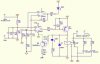
A point thats puzzling me is the wide limits set for the comparator, the Sim shows limits of +4V and +10V.
This suggests that once the comp reads a voltage of greater than 10V, the SUN is connected to the motor
and will remain connected until SUN falls just below +4V.
I cannot see that the PV would be able to drive the motor at 4Vish.

At the <4V cut out limit, a full 24V is applied to the motor, thats a motor voltage change of 20V!.

The circuit as designed dosnt allow for the possiblity of PV[SUN] open circuit voltage of reading > 10V when the motor is switched over to the +24V.
This causes the comp to switch on/off at the lower limit of 4V.

Could you give details of the PV [solar panel] and the motor, also whats the 'system' doing, simply: whats it for.?

What limits on SUN high/low voltage do you require.

Im sure we can come up with design ideas.:)
Regards
 
Last edited:
The panel is 10W and the voltage max recorded is 18V. The motor is 24VDC / 0.8A and will operate down to 4V / 30mA. The 180 Ohm simulated load resistor allowed the panel to reach 13V / 70mA before switching to SUN. This was enough power to prevent it from going below the 4V threshold when connected to the motor.

I'll have to verify the prototype PCBA with the schematic to see why you get 10V upper threshold in simulation and I observe 13V.

Can you help me get the LM393 and relay on LTSpice?
 
Yes, I've already accomplished this. It does require a delay off though. I think maybe C25 may be a problem as it is being charged by the 24V+ and discharges upon switching to the lower voltage SUN. I'm removing it now to see how it affects the performance.


Sorry, I misunderstood what you said before this.

There are time delay realays, but I think they're expensive. Alternatively, you can use a simple timer configured as a delay element.
 
Last edited:
The panel is 10W and the voltage max recorded is 18V. The motor is 24VDC / 0.8A and will operate down to 4V / 30mA. The 180 Ohm simulated load resistor allowed the panel to reach 13V / 70mA before switching to SUN. This was enough power to prevent it from going below the 4V threshold when connected to the motor.

I'll have to verify the prototype PCBA with the schematic to see why you get 10V upper threshold in simulation and I observe 13V.

Can you help me get the LM393 and relay on LTSpice?

hi 1ab,

This is from the Yahoo Spice Files. [LM393]

BTW: whats the motor on the SUN project actually driving, just curious.:)

EDIT:Look here for relays.
**broken link removed**
 

Attachments

  • LM339_LM393.zip
    5 KB · Views: 126
Last edited:
Success!

Thanks Eric for the help with the components. LTSpice is a neat tool. Better if I knew how all of the details worked. I've learned a lot through this project.

With MrAl's help offline, we were able to make some minor mods to the circuit design. I had tested putting a simulated load resistor across the panel leads when not in solar mode in order to keep the voltage from jumping past the upper threshold but I had to use a PLC to make it work.

MrAl suggested using a NPN transistor with a risistor from the Q4 output that would "switch" on the simulated load resistor. My handy Radio Shack 300 kit from my youth had a C1740 NPN transistor in it that worked beautifully.

I attached the modified circuit diagram.

THANKS FOR ALL YOUR HELP!!
 

Attachments

  • SolarCompare2.JPG
    SolarCompare2.JPG
    27.6 KB · Views: 287
Status
Not open for further replies.

Latest threads

New Articles From Microcontroller Tips

Back
Top