*** Warning: Long read ***
I am currently repairing a Creston AV2 Control System. For those who are unfamiliar with this device, it is a microprocessor-based remote control system that can communicate with intelligent devices capable of one or two-way communication via RS232/422/485 serial, relay contact closures, I/O logic ports, and Infrared serial signals. I have acquired this control processor and it was dead when I picked it up from my friend.
First thing I did when I got home was plug it into an AC outlet to verify it was indeed dead. Then, I took off the top cover and unplugged the SMPS from the main bus board that hold the main processor and control board together. Measured the output of the SMPS and got +24V DC. Plugged it back in and the voltage goes to zero. This tells me that there is a shorted component somewhere in one of the boards. Disconnect the SMPS again and took a resistance reading between the power rails. It read around 2 to 3 ohms. So, near shorted which confirms my suspicion.
Next, I was able to identify that the bad component is on the main board by unplugging the other board from the bus board. With only the main board connected to the bus board, I connected my programmable DC power supply to the power terminals and proceeded to inject voltage and current into it. First, I started with 1.5V. Felt around both sides of the main board to find out which component is very hot to touch. Didn't find anything. I proceeded to increase the voltage to 3V, at this point, the current went up to nearly 2A. I know this is excessive. After a few minutes, I smelled something burning. I narrowed it down to the area around the black 4-pin phoenix-type connected called the CRESNET port. Felt around and found a component labelled Z3 on the board that is very hot to the touch. Nailed it!
The CRESNET port has 4 terminals. The center pair is for the proprietary control signal to communicate with other Crestron devices like touchscreens and button control panels and the outer pair which is the 24VDC +/- supply (used tol power-up the input devices or other intelligent devices that have CRESNET (lighting dimmer modules come to mind). The built-in SMPS has a 50-watt capacity. The CRESNET power output pins take its power from the SMPS along with the main board and the control board.
Component Z3 has a label, AD13 MM. I looked everywhere on the web for a data sheet for this component but I could not find it. When I contacted Crestron, they refused to give me any information about it. They said to send the whole unit back to them for repair service. I am in no position to pay for expensive shipping to NJ (from BC Canada) and back just so they can replace a component that's worth $0.10. Also, this AV2 processor is more than 13 years old and already an obsolete product.
I would like to seek the help of knowledgeable people in this forum to identify Z3 for me. I suspect that the AD13 part number is not real. It is a proprietary part number for a common part that Crestron ordered from a semiconductor company.
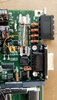
Z3 straddles the 24V power rails. When I measured it in-circuit, I get 3 ohms across regardless of polarity. I have included photos in this post to show you the main board and where this Z3 component is located. The large fuse beside it sits in series to the +24 VDC line. I have confirmed that one end of Z3 sits on the (-) side of the power rail and the other is on the (+) side.
I suspect that Z3 is a zener diode but not sure. I suspect that it is meant to protect the main board from someone connecting something with 24VDC into the green port that is outputting 24VDC. Or, prevent damage by accidentally connecting a load in reverse polarity.
I am seeking some thoughts and recommendations for a substitute part. Thanks! I know this is a long read but I think sharing this much info is essential.
I am currently repairing a Creston AV2 Control System. For those who are unfamiliar with this device, it is a microprocessor-based remote control system that can communicate with intelligent devices capable of one or two-way communication via RS232/422/485 serial, relay contact closures, I/O logic ports, and Infrared serial signals. I have acquired this control processor and it was dead when I picked it up from my friend.
First thing I did when I got home was plug it into an AC outlet to verify it was indeed dead. Then, I took off the top cover and unplugged the SMPS from the main bus board that hold the main processor and control board together. Measured the output of the SMPS and got +24V DC. Plugged it back in and the voltage goes to zero. This tells me that there is a shorted component somewhere in one of the boards. Disconnect the SMPS again and took a resistance reading between the power rails. It read around 2 to 3 ohms. So, near shorted which confirms my suspicion.
Next, I was able to identify that the bad component is on the main board by unplugging the other board from the bus board. With only the main board connected to the bus board, I connected my programmable DC power supply to the power terminals and proceeded to inject voltage and current into it. First, I started with 1.5V. Felt around both sides of the main board to find out which component is very hot to touch. Didn't find anything. I proceeded to increase the voltage to 3V, at this point, the current went up to nearly 2A. I know this is excessive. After a few minutes, I smelled something burning. I narrowed it down to the area around the black 4-pin phoenix-type connected called the CRESNET port. Felt around and found a component labelled Z3 on the board that is very hot to the touch. Nailed it!
The CRESNET port has 4 terminals. The center pair is for the proprietary control signal to communicate with other Crestron devices like touchscreens and button control panels and the outer pair which is the 24VDC +/- supply (used tol power-up the input devices or other intelligent devices that have CRESNET (lighting dimmer modules come to mind). The built-in SMPS has a 50-watt capacity. The CRESNET power output pins take its power from the SMPS along with the main board and the control board.
Component Z3 has a label, AD13 MM. I looked everywhere on the web for a data sheet for this component but I could not find it. When I contacted Crestron, they refused to give me any information about it. They said to send the whole unit back to them for repair service. I am in no position to pay for expensive shipping to NJ (from BC Canada) and back just so they can replace a component that's worth $0.10. Also, this AV2 processor is more than 13 years old and already an obsolete product.
I would like to seek the help of knowledgeable people in this forum to identify Z3 for me. I suspect that the AD13 part number is not real. It is a proprietary part number for a common part that Crestron ordered from a semiconductor company.
Z3 straddles the 24V power rails. When I measured it in-circuit, I get 3 ohms across regardless of polarity. I have included photos in this post to show you the main board and where this Z3 component is located. The large fuse beside it sits in series to the +24 VDC line. I have confirmed that one end of Z3 sits on the (-) side of the power rail and the other is on the (+) side.
I suspect that Z3 is a zener diode but not sure. I suspect that it is meant to protect the main board from someone connecting something with 24VDC into the green port that is outputting 24VDC. Or, prevent damage by accidentally connecting a load in reverse polarity.
I am seeking some thoughts and recommendations for a substitute part. Thanks! I know this is a long read but I think sharing this much info is essential.
Attachments

Last edited:
