Continue to Site

Welcome to our site!

Electro Tech is an online community (with over 170,000 members) who enjoy talking about and building electronic circuits, projects and gadgets. To participate you need to register. Registration is free. Click here to register now.

  • Welcome to our site! Electro Tech is an online community (with over 170,000 members) who enjoy talking about and building electronic circuits, projects and gadgets. To participate you need to register. Registration is free. Click here to register now.

Need help identifying and sourcing part for CD Changer

Status
Not open for further replies.

Bob J

New Member
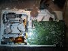
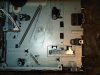
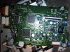
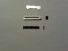
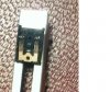
I have a CD changer in my 1995 Mercedes E320 which has given me problems. While taking it apart, I forgot to remove a couple of screws and broke the end off a switch which indicates that the cartridge has been loaded. I can't repair it so I need to replace it. I believe the changer was made for Mercedes by Alpine. I have searched the web and found lots of photos of similar changers and they all seem to be essentially the same, so I'm hoping the part I need won't be too difficult to obtain. I have attached 3 images. One shows the overall changer; the second shows the part (circled) that I broke in the location it's supposed to be; the third shows the part mounted on the circuit board. The switch has a number "719E" printed on it. It goes onto the circuit board in the VR101 location. Can anyone help me identify what the part is called so that I can search for a replacement? Or if you know where I can get the part that would be even better. Thanks for your help. Bob
 

Attachments

  • CD Changer Overview.jpg
    CD Changer Overview.jpg
    452.9 KB · Views: 433
  • CD Changer Slider Switch.jpg
    CD Changer Slider Switch.jpg
    360.8 KB · Views: 344
  • CD Changer Circuit Board.jpg
    CD Changer Circuit Board.jpg
    417.3 KB · Views: 624
That actually looks like a slide potentiometer (VR101 = "variable resistor 101"?); I would desolder it, measure the resistance range, then -carefully- measure it (both in imperial and metric units - H x W x L) - then head over to DigiKey/Mouser and look it up...

It's probably common.
 
Last edited:
Thanks for the prompt response. It certainly looks like a slide potentiometer now that I look it up on Mouser. Another question - where I broke it is at the end where the 3 connectors are located. So there is no attachment to the sliding mechanism. Is there any way to read the resistance accurately directly off the remaining part?
 
Well, it looks like the slide portion is "stuck" at one end of the travel - if you can move it away from that end a little bit (after removal), then there should be 3 pins on the part that you can ohm out with a multi-meter; set the meter to something like 10K ohms, and put the leads across two of the pins; with the slide positioned part way (if you can roughly center it, even better), two of the pins will measure one value, and the other too will measure a lower value. You want the higher value (of course, if it goes out of range, move to the next higher setting on the meter). That will tell you its value in ohms; with the size measurements and that, you can at least find something close. Note that you will probably want to measure the length of the piece that broke off, and check the specs for the length of that piece two (should be on one of the last sheets listing dimensions). Find something close, or longer (and then do some hacking on it to reduce it to the right length - take a dremel or x-acto to it)...
 
Last edited:
Thanks for the great instructions for measuring the resistance. The problem I have is that the pins are on the part that broke off so they are no longer connected to the part. Is there a way to measure the resistance from the remaining piece?
 
Well, since it is hosed anyhow, you could take it apart (after measurement, of course) - you should see a strip underneath the slider (likely black colored), with perhaps a second strip next to it; one will be a "zero resistance" strip, while the other will be the resistance strip, and likely has the connection for the pins on either end. The second strip likely has a connection on only one end. If you measure it first, then take it apart and take some clear pics of it, I might be able to help you better...?
 
I've attached 3 images. The first shows all the parts - the cover, the resistance strip, the slider, and the broken pin section. The second shows the resistance strip. It may be difficult to see, but their are two wide sections on either edge and a thin section in the middle. The thin section is attached on the left side to the upper thick section. The third shows the bottom of the slider. Hope that helps. Thanks again for all your advice. Sorry if the photos aren't as clear as they should be. I'm using my Blackberry and don't have a camera with me. Bob
 

Attachments

  • Potentiometer Parts.jpg
    Potentiometer Parts.jpg
    167.1 KB · Views: 352
  • Resistance Strip.jpg
    Resistance Strip.jpg
    389.1 KB · Views: 319
  • Slider.jpg
    Slider.jpg
    42.4 KB · Views: 330
Probably the middle black line is the "zero resistance" rail, while the other two are "half-resistance" rails; you should be able to measure them by touching your multimeter leads to the end of each one; likely, the top and the bottom rails will have the same resistance, while the middle rail should be zero or near zero. However it works out, two of the rails will be the same or near the same, while one of the rails should be near zero. The value of the potentiometer then should be the value of the two rails with resistance added together (this is really assuming that the potentiometer is linear, of course - which is likely is for this application). BTW - there were no markings on the outside of the potentiometer? Most of time it is stamped or inked on (not always, though)...
 
It was hard to get a steady reading on two of the rails. One of the outer ones reads 0 while the other is 10KΩ. The middle one (it's attached to the 10K one at the bottom) reads 600Ω. I've tried three ohmeters and get the same results on all of them. By the way the number stamped on the cover was 719E.
 
I'm going to guess its a 10KΩ potentiometer; I base that on what I can see in the pics, which seems to show that there isn't a "center wiper" (there are two outer ones, though - at least what I see in the 3rd pic). The three pins on the potentiometer - how do they appear to be connected on the PCB (when they were connected, that is); do all three have traces which connect to another component on the board, or do only two? I am trying to determine if the device is being used as a rheostat for current or as a voltage divider. Maybe you can look on Mouser/Digikey and see if you find anything like a "10KΩ w/ 600Ω limiting resistor" or something...?
 
Thanks for all your help. I don't have time right now to continue the research but will pick it up in a couple of weeks. I learned a lot from you which is appreciated.
Bob
 
Thanks for all your help. I don't have time right now to continue the research but will pick it up in a couple of weeks. I learned a lot from you which is appreciated.
Bob

Well, I'm glad I was able to help in some manner; if/when you return to it and have questions, post here again since I am monitoring the thread...
 
Hi. I would like to know if you have founded this compomponent. Now I have the same problem but I think that it will be very difficult to find this potentiometer :S
 
I have another idea for you. Measure end to end for the top, middle and bottom slider.

Three connections bother me a bit. I can't figure out how 3 connections would be made. The end to end resistance of the top and bottom rails COULD make up 1/2 the value of the potentiometer.

Also wondering if you could tell anything with the slider taped to the resistive element. There is something I'm missing.
 
Status
Not open for further replies.

Latest threads

New Articles From Microcontroller Tips

Back
Top