Soltu
New Member
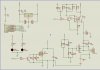
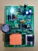
I collect this circuit from my local market. I want to write code like this circuit so that is work like that. Now I will say how this circuit works.
This circuit works in two mode:
A- When Circuit connected with transformer
1. When the circuit is run, the charging LED will blink three times with 1000ms delay.
2. After three times blink It will start blink again for 250ms. Relay and Moster will on. That means charging is start and output is off.
3. If Battery voltage exceeds adc 2.12v then the charging LED Blink will stop but charging LED stay ON. Relay will OFF but Mosfet stay On. That means battery full charged complete.
B- When Circuit not connected with transformer
1. When I start a DC fan with battery and the battery voltage drops below adc 1.58v then this low LED will on and the mosfet will be on which the output is closed.
Here is my code. I facing a problem with this code. low battery led working fine, charging also working fine but one problem now I faced, that is, when the battery charge is full, the relay chattering. But it should be when the battery charge is fully charged, the relay will off and charge LED will On. So what's wrong in my code? Plz help me..
I shared circuit diagram and picture.
This circuit works in two mode:
A- When Circuit connected with transformer
1. When the circuit is run, the charging LED will blink three times with 1000ms delay.
2. After three times blink It will start blink again for 250ms. Relay and Moster will on. That means charging is start and output is off.
3. If Battery voltage exceeds adc 2.12v then the charging LED Blink will stop but charging LED stay ON. Relay will OFF but Mosfet stay On. That means battery full charged complete.
B- When Circuit not connected with transformer
1. When I start a DC fan with battery and the battery voltage drops below adc 1.58v then this low LED will on and the mosfet will be on which the output is closed.
Here is my code. I facing a problem with this code. low battery led working fine, charging also working fine but one problem now I faced, that is, when the battery charge is full, the relay chattering. But it should be when the battery charge is fully charged, the relay will off and charge LED will On. So what's wrong in my code? Plz help me..
Code:
   if(GP3_bit == 1){
      if(adc_voltage <= 2.120){
        led_blink = 1;
        RELAY = ON;
        MOSFET = ON;
        low_led = OFF;
      }

   else  {
     charge_led = ON;
     led_blink = 0;
     RELAY = OFF;
     MOSFET = ON;
     low_led = OFF;
     }
   }


   if(GP3_bit == 0){
    if(adc_voltage <= 1.58100){

      charge_led = OFF;
      led_blink = 0;
      RELAY = OFF;
      MOSFET = ON;
      low_led = ON;
    }
   else
    led_blink = 0;
    charge_led = OFF;
    RELAY = OFF;
    MOSFET = OFF;
    low_led = OFF;
   }
   }
I shared circuit diagram and picture.