TiagoGuerra
New Member
Hi all!
First I would like to say that I really don't have great experience with electronics, apart from soldering some basic things, but I aprreciate any help you can give me!
I've been given a Fender Mustang GT40 guitar amp that has a problem. When I turn it on the LCD lights up but the Fender logo doesn't appear, and obviously it won't load the presets either, so I get no sound coming from the app. It appears to me that by some reason the operative system of the amp is not loading, and I've tried all the solutions I've come across the Internet of trying to turn on the amp while holding certain buttons to do firmware updates, or factory resets, or other things...
In some forums I noticed that other people had this problem too, but I couldn't find any solution anywhere. I've also tried to plug the amp to my PC via USB and do firmware updates, but when I turn the amp on I just hear the USB sound that you get when you connect something to the PC and nothing appears on the PC and nothing happens to the amp besides the LCD lightning up.
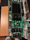
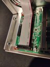
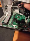
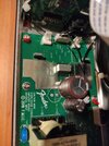
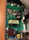
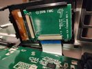
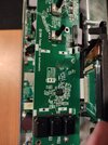
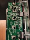
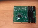
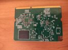
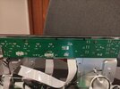
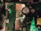
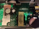
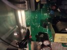
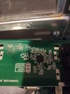
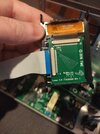
I've opened the amp but I don't see any broken solder joints or unplugged cables that could cause something like that.
Is there any way to unplug something on the amp that would cause a factory reset? I really need the amp to work since I don't have any other guitar amp at the moment.
Thanks for the help!
First I would like to say that I really don't have great experience with electronics, apart from soldering some basic things, but I aprreciate any help you can give me!
I've been given a Fender Mustang GT40 guitar amp that has a problem. When I turn it on the LCD lights up but the Fender logo doesn't appear, and obviously it won't load the presets either, so I get no sound coming from the app. It appears to me that by some reason the operative system of the amp is not loading, and I've tried all the solutions I've come across the Internet of trying to turn on the amp while holding certain buttons to do firmware updates, or factory resets, or other things...
In some forums I noticed that other people had this problem too, but I couldn't find any solution anywhere. I've also tried to plug the amp to my PC via USB and do firmware updates, but when I turn the amp on I just hear the USB sound that you get when you connect something to the PC and nothing appears on the PC and nothing happens to the amp besides the LCD lightning up.
I've opened the amp but I don't see any broken solder joints or unplugged cables that could cause something like that.
Is there any way to unplug something on the amp that would cause a factory reset? I really need the amp to work since I don't have any other guitar amp at the moment.
Thanks for the help!