blokroknbeats
New Member
I am hoping someone here can help me. I am very new at this so i am sorry if this is a stupid question. I install electronics in cars, audio/video etc. On my current personal project i am attempting to add an aftermarket cruise control and control it using a infiniti g35 steering wheel (not in a g35)
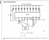
There are 4 switches for the cruise control each with a resistor. Ground is supplied to each switch and the outputs pass through resistors to a common output wire. Each switch has a different resistor value. I am trying to find a device or circuit that will allow me to have a separate output (either ground or 12v with at least 150ma to drive a spdt relay) for each switch. This will be in a car so i am using 12vdc.
Sorry if this is basic but i would appreciate any help, even if its just a point to the right direction.