Hello all,
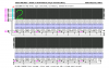
I have been working on trying to get this large led matrix that I have working which is 64x16.
The 16 rows are attached to the (-) of the leds in the row and the 64 columns attach to the (+) of each led in the column.
I have an arduino and a ton of shift registers already so I decided to try that out. I have ten 74hc595 shift registers controlling the 64 columns.
I also have two more 74hc595 to control the grounds. They are attached to 16 transistors.
I currently can easily control any given row and in any way but when i try and go through the rows to display one solid image over the entire matrix I get ridiculous flickering and ghosting.
Right now the 12 shift registers are all chained so the first 2 registers are the ones for the grounds and the rest are to drive the leds high.
I need to ensure a strong brightness and smooth animation since this display will be viewed heavily.
Am I moving in the right direction? Or is there a better way of accomplishing this.
Thank you in advance for any help.
Last edited: