Continue to Site

Welcome to our site!

Electro Tech is an online community (with over 170,000 members) who enjoy talking about and building electronic circuits, projects and gadgets. To participate you need to register. Registration is free. Click here to register now.

  • Welcome to our site! Electro Tech is an online community (with over 170,000 members) who enjoy talking about and building electronic circuits, projects and gadgets. To participate you need to register. Registration is free. Click here to register now.

Need help building a class D amplifier

Status
Not open for further replies.

munky

New Member
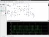
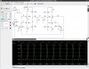
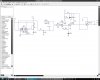
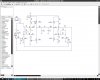
Hello, I'm building a class D amplifier for my school project and I need a lot of help because I'm so lost. The amp uses 12Vdc as its input, the frequency range I'm trying to get is 20Hz to 20kHz, the speaker is 4 ohms, and I'm trying to get as much power possible without the use of a DC-to-DC converter. I've been using CircuitMaker2000 to simulate my circuit. Please tell me what I'm doing wrong, since my H bridge does not work at all. Thanks.
 

Attachments

  • pwm.JPG
    pwm.JPG
    122.6 KB · Views: 399
  • hbridge.JPG
    hbridge.JPG
    133.3 KB · Views: 387
Here are a few points.

U3, the OP177, doesn't seem to have a power supply.

R18 and R19 seem far too low because they will make Q6 and Q10 too difficult to turn on.

Q5 is the wrong way up.

R7 and R15 are pointless, as 10 k:eek:hm: in parallel with 50 :eek:hm: does nothing.

The simulator should tell you what waveforms you are getting. Check the waveforms at various points through the circuit to see where it is going wrong.
 
You need to run the PWM at a much higher frequency than the bandwidth of your system, I would try to go up to 200kHz if you can but you might be able to get away with 100kHz. This can make the design of the switching circuit very challanging as getting MOSFETs to switch that fast whilst minimising losses isn't easy. Then there's building a good output filter that happilly passes the audio band but rejects all the RF.
 
Hero999 said:
Then there's building a good output filter that happilly passes the audio band but rejects all the RF.

You don't have to reject all the RF, just make it small enough - class D amps commonly have a switching residue on the output. Assuming the values in his example above were correct, then that degree of filtering is probably fine.

But as you say, the higher the switching frequency, the easier the filtering is.
 
I made notes on the schematic:
 

Attachments

  • class-D H-bridge.PNG
    class-D H-bridge.PNG
    38.8 KB · Views: 281
Some modifications

Hey, I changed a few things around according to the replies. I tried to make R5 and R8 bigger values, but I got a really weird signal, see Hbridge2 attachment. When I left R8 and R5 alone, I get a much better signal, but there is some crossover. I was wondering, what is the best way to remove crossover? Can the totem pole transistor configuration work? Thanks
 

Attachments

  • hbridge2.JPG
    hbridge2.JPG
    163.3 KB · Views: 194
  • crossover.JPG
    crossover.JPG
    158.1 KB · Views: 238
The 2N3906 PNP transistors don't have a resistor to turn them off quickly. So they slowly float off then they turn off too late.
 
i thought a class d amplifier had high crossover distortion due to the transistors being on for less that 180 degrees. and they were mainly used to pulse tank circuts in radio?
 
Gaston said:
i thought a class d amplifier had high crossover distortion due to the transistors being on for less that 180 degrees. and they were mainly used to pulse tank circuts in radio?

Doesn't matter, it's a PWM switching design, crossover distortion doesn't apply as the transistors aren't used in a linear fashion.
 
what are the transistors doing? is this for a car amp where the voltage needs to be stepped up? i never did understand exactly how they do that
 
Gaston said:
what are the transistors doing? is this for a car amp where the voltage needs to be stepped up? i never did understand exactly how they do that

The transistors are switching ON and OFF at a fairly high frequency, and the width of the pulses is controlled by the audio input, and the audio recovered afterwards with an LC filter. It's actually two amplifers bridged together, this effectively gives twice the supply voltage, and four times the output power into the same impedance.

For higher power use in cars you would use an inverter to increase the supply voltage, otherwise single ended is 4W maximum and bridged 16W maximum (both into 4 ohms).
 
thanks, i'm begining to understand now. i have seen the switching pro amps that are ultra light and only take up one to two rack spaces, but i thought they were useing switch mode power supplies instead of big transformers. i didn't know they were using pwm for the audio.
 
Gaston said:
thanks, i'm begining to understand now. i have seen the switching pro amps that are ultra light and only take up one to two rack spaces, but i thought they were useing switch mode power supplies instead of big transformers. i didn't know they were using pwm for the audio.

They often use both, just like a switch-mode supply they are more efficient and require much smaller heatsinks.

In fact, conventional power supplies are quite common (because of their lower price), so often it's just a class D amplifier that makes them small.

By 400W+400W mixer/amp uses both, so is small and light (which was a major selling point for it).
 
A linear amplifier needs big heatsinks and still gets hot.
A class-D amplifier switches so its output transistors stay fairly cool.
Texas Instruments make class-D amplifier ICs that have hundreds of Watts of output and the little surface-mount IC does not need a heatsink.
 
audioguru said:
The 2N3906 PNP transistors don't have a resistor to turn them off quickly. So they slowly float off then they turn off too late.

Hey, where should I put the resistor to make the 2N3906 transistors turn off quickly?? Sorry, I'm kind of slow on this stuff. Thanks
 
Hello, I was wondering, what is the best way to impedance match because when I combine my PWM circuit with my H bridge circuit, the simulations won't run at all. Thanks.
 

Attachments

  • hbridge.JPG
    hbridge.JPG
    87.4 KB · Views: 202
  • pwm.JPG
    pwm.JPG
    107.7 KB · Views: 169
  • combined.JPG
    combined.JPG
    33.7 KB · Views: 172
Status
Not open for further replies.

New Articles From Microcontroller Tips

Back
Top