Continue to Site

Welcome to our site!

Electro Tech is an online community (with over 170,000 members) who enjoy talking about and building electronic circuits, projects and gadgets. To participate you need to register. Registration is free. Click here to register now.

  • Welcome to our site! Electro Tech is an online community (with over 170,000 members) who enjoy talking about and building electronic circuits, projects and gadgets. To participate you need to register. Registration is free. Click here to register now.

Need Direction...

Status
Not open for further replies.

Rgardner928

New Member
I'm extremely new to this and I don't know where to go. I just joined your forum, So let me start off by saying that.

I could probably do it myself as I have basic soldering gun and tools. But I don't know how or where to begin. Maybe somebody out there knows what I need and can help me to accomplish what I'm looking for quickly.

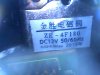
I'm looking for someone to make or help me learn to make a circuit board that gets power from a 12v wall wart. Amperage is flexible to whatever is needed. Once said board is powered up it needs to be able to turn on a 12-volt normally closed water solenoid that's controlled by a waterproof motion sensor on a lead that's about 12" long.

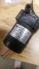
And this same circuit board must also have two water level sensors on 6" leads. So that when the water reaches the top sensor it kicks on a small 12-volt water fountain style pump. When the water level gets down low enough to expose the lower sensor the pump shuts back off.

Both have to work independently of each other without interference from the solenoid or the fountain pump or any sensors. Only want one similar barrel style plug to control it all from.

Thanks in advance
 
OK, the two parts are separate, just working from the same 12V supply.

The water level part would use a relay wired in a self-latching circuit, like this:

The float switches replace the push buttons; both float switches are set so they close when the water level is higher.

The high level switch acts as the top button to latch the relay in, the low level switch acts as the bottom button, disconnecting the "hold in" link through the relay contact when the level drops too much.

The second contact on the relay switches power to the fountain pump.


The motion sensor output contact could directly operate the water solenoid valve, if the contact rating is high enough. Otherwise, use the contact to switch power to a relay coil and use a contact on the relay to switch power to the solenoid.

(Omit the push-to-break switch and the connection it uses through the relay contact in that relay drawing, so the motion sensor acts as the top switch. Without the latch contact wiring, the relay just follows the on/off action, but can switch much higher currents, depending on the exact relay you get).


The easiest ones to work with are either cradle relays or octal / 11 pin types that you can get with screw terminal bases.
Cradle style are typically rated to about 5A (some 10A) through the contacts, octal are normally 10A.

From a quick look on ebay; rectangular / cradle style:
**broken link removed**

Octal relay,
And a base to plug it in to:

The 11 pin style look similar but have three change-over contact sets and three more pins.

The smaller cradle type generally tale a bit less current to operate the coil.


Note that in a practical circuit the relay coils and solenoid valve need "flywheel diodes" across the coil connections.
Without those, the contacts controlling them will arc due to the inductive flyback kick from the coil.

This shows the basic connection, straight across the coil terminals with the diode cathode (band marking) to the positive side.
1N4000 series diodes are easy to get and OK for that use in small power circuits like that, eg. 1N4002 or 1N4007 ( or anything in between).
 
Wow, you seam very helpful. And you explained vividly. But, I'm lost and I did follow a dam thing! I think I got you said to do relays. But once this is enclosed, if a relay goes bad, there will not be a way to access them to replace them. That's why I thought a circuit board. But I maybe thinking differently then what your trying to explain to me.
Sorry I didnt follow 100%.
 
If it is to be all electronic, it will be rather more complex & expensive - and you need to give the exact specifications of the valve and pump you want to use.

These are typical float switches - either side mount, through the container wall

or top mount, with various length stems or even two on one stem

Note that any electrical or electronic system has a chance of failure, you should really design so it is possible to access the control unit (of whatever type) in that event.
It's basic engineering, allowing for Murphy's law - "If anything can go wrong, it will".
 
So I'm trying to reproduce something already in production, that the company has gone out of business. I'm in the process of acquiring the patients but the tooling and productions are not able to get a hold of. I need to redesign what's there slightly. And i know what they have. I can post pictures of some of the components, so you understand.
 
Pump that pumps the water out. Its.back and I ordered a new one.
 

Attachments

  • 20190526_173338.jpg
    20190526_173338.jpg
    444.2 KB · Views: 124
Solenoid, that comes on when the sensor, which I have yet to find, triggers it.

Pictures are taking with a borescope
 

Attachments

  • 20190526_173100.jpg
    20190526_173100.jpg
    303.1 KB · Views: 117
Circuit board

Pictures are taking with a borescope
 

Attachments

  • 20190526_173318.jpg
    20190526_173318.jpg
    302.1 KB · Views: 126
  • 20190526_173136.jpg
    20190526_173136.jpg
    293 KB · Views: 109
Front side of water sensor looks to be covered in black silicone and the back side with the white wire.
 

Attachments

  • 20190526_173240.jpg
    20190526_173240.jpg
    278.8 KB · Views: 105
  • 20190526_173157.jpg
    20190526_173157.jpg
    312.6 KB · Views: 105
You could use a 555 timer for the water level sensing and latching, and a PIR motion sensor module (readily available and cheap) to drive the solenoid through a buffer transistor. A circuit might look like the following:
118544


Each water level switch is simply a pair of wires with exposed tips. The resistance of the water between the pair of wires should be less than 200k for the circuit to work with the 470k resistors I drew.
 
Sounds like what there now for the most part. What do you thing the parts would cost me to make myself, or have someone make for me?

Thinking maybe having terminal connections like the picture so i can wire in the solenoid and one for the pump. This way its easier to swap them when they need to be replaced.
 

Attachments

  • 20190526_224254.jpg
    20190526_224254.jpg
    95.3 KB · Views: 103
Parts are under $20; less if you are willing to wait for shipping from China. If you want someone to make it for you, which country are you in?

Terminal blocks are good. You'd want to have them inside the enclosure, with some waterproofing mechanism on the wire entry ports.
 
This is a dog water bowl. The electricals is sealed in a dry location.

As for the parts, I can wait for china parts. As for someone making it. I'm in the US on the Pacific side.
 
Status
Not open for further replies.

Latest threads

New Articles From Microcontroller Tips

Back
Top