Electro Tech is an online community (with over 170,000 members) who enjoy talking about and building electronic circuits, projects and gadgets. To participate you need to register. Registration is free. Click here to register now.
Welcome to our site! Electro Tech is an online community (with over 170,000 members) who enjoy talking about and building electronic circuits, projects and gadgets. To participate you need to register. Registration is free. Click here to register now.
It looks like they just use it to drive the Relay. Try using the relay Driver circuit from this one that I already posted and use the rest of the circuit from your diagram.
The very old SL100 metal-cased transistor has a load of only 12V/200 ohms= 60mA. Any little NPN transistor can drive it if the base current through R5 is increased a little.
sir i know these circuits are same.only one difference is present in my circuit i.e
when the water doesnot com from the well or dry.circuit will beep.and alert us.
sir i know these circuits are same.only one difference is present in my circuit i.e
when the water doesnot com from the well or dry.circuit will beep.and alert us.
If you look at the Diagram Close I modified the circuit you originally posted and removed the SL100 Transistor and replaced it with the drive circuit from the other diagram.
The yellow one now has a BC337 instead of the SL100 and BC548 both are gone from the schematic and I changed the resistor value of R4 and R5 is gone.
respected sir i shall be very thankfull to u.now i will make hardware this ckt if any problem find so again i will tell u
thanks.........................
The circuit you attached has a very old SL100 transistor driving a 200 ohm relay coil from a 9V supply. Then its current is only 9V/200 ohms= 45mA. Any little NPN transistor can drive the relay coil.
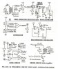
I need to design triggering circuit for single phase full wave rectifier. In the circuit, it consist of SL-100.. But, there's no Sl-100 in my simulation software. My ques is, can i change SL-100 to another transistor ? the circuit is look like dis..
You saved your schematic as a tiny and fuzzy JPG file type instead of as a larger very clear PNG file type.
So we cannot see the details of the relay that is driven by the old Indian SL100 transistor.
You must determine the relay coil current and if the base current is enough to turn on a transistor that drives that much current. The 10k base resistor value seems to be too high, but maybe because it is driven from a low current Cmos gate.
The Cmos ICs with a 12V supply will have an output current of 11mA to 22mA if it does not have a current-limiting resistor. But then the output transitor of the IC will get too hot if it directly drives the base of an NPN transistor that has its emitter grounded.
But the 10k base resistor limits the base current of the transistor to only about 1.2mA so the transaistor's load current can be only 12mA to 24mA.
The circuit appears to be designed by somebody who knows nothing about transistors.
Thats why i need to re-design this circuit. But, with my current knowledge about this circuit, m not sure whether i can design my own circuit for my project. hope u can advice me...
Yup, i only need a small collector current for the transistor. The current will be used to trigger the gate of the SCR... (just to switch the SCR into ON state).
Yup, i only need a small collector current for the transistor. The current will be used to trigger the gate of the SCR... (just to switch the SCR into ON state).
No.
You and I do not know how much current the SL100 transistor provides to the pulse transformer. It might be a lot of current.
Look at the 51 ohms/2W resistor in series with the pulse transformer. If it dissipates 2W for a moment then its current is 198mA. Then the base current of the transistor needs to be 9.9mA to 19.8mA, not just 1.2mA. Then the value of the 10k base resistor is much too high.
Maybe ur is right. But isnt the function of that 10k resistor is to limit the base current through the SL-100 therefore it does not burn out the transistor?
hmm... sorry, but i didnt know much about that circuit designed by book authors.. its just a reference for me in order to construct the triggering circuit. Hm.. Do you have any idea / proposed solution for that circuit ?
If we use the base current to define (limit) the collector current, then the transistor won't turn fully ON. This is worst case for a transistor switch: Current may be 100mA and Vce 6V, a dissipation enough to get it pretty hot. (The reason for 100mA is that the unsaturated gain is more like 50 to 100.) It may sound ironic, but to protect the transistor it must get enough base current to turn fully ON when you want it.
If you supply 10mA (base resistor about 680R). to the base of a common transistor it'll give you a lot more current even if it isn't technically in saturation. (I can't suggest a transistor because your profile says you are no where.) If Vcc is 12V, the 51 ohm resistor will limit the current to about (11/51) = 215mA anyways, even so that's only if the pulse transformer is allowed to saturate. The oscillator at 4kHz would provide pulses of 12.5 microseconds, so it all depends on the transformer.
One thing that designers naively do with pulse transformer circuits is to put the diode directly across the transformer primary. This slows down the recovery and severely limits the flyback energy available to the thyristor. (The trade off is that Vce is doubled.when in flybaack. It's 12V*2 or 24V.) Changes shown below.
This site uses cookies to help personalise content, tailor your experience and to keep you logged in if you register.
By continuing to use this site, you are consenting to our use of cookies.

")