Continue to Site

Welcome to our site!

Electro Tech is an online community (with over 170,000 members) who enjoy talking about and building electronic circuits, projects and gadgets. To participate you need to register. Registration is free. Click here to register now.

  • Welcome to our site! Electro Tech is an online community (with over 170,000 members) who enjoy talking about and building electronic circuits, projects and gadgets. To participate you need to register. Registration is free. Click here to register now.

Need assistance pushing more current to LEDs

Status
Not open for further replies.

Team PSU

New Member
Hello all,
I've been working on an IR transmitter/receiver circuit for some time now. I have the correct signal to send to my receiver but I need assistance increasing the range of the system.

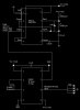
I have a 555 timer bursting a signal to this highspeed IR transmission chip:
https://www.electro-tech-online.com/custompdfs/2009/04/TXIRHS_DOC.pdf
The output of the 12F629 chip can only source 25mA (I believe) and I have it running to a power rail. The power rail has 4 setups of a 50ohm resistor and 870nm IR led back to ground.

I have the Vishay TSOP7000 IR receiver modules wired correctly and I can get the two units to talk to each other. However, I can't get over 6-7 feet of range.

I tried to wire in a 2N2222 transistor but couldn't get it to function correctly. I also tried a LM741 Op-amp but it distorted my signal, and a IRF510 Mosfet, but it distorted the signal too.

Can someone show me a schematic or give me guidance on how to push more current through the LEDs? Thank you in advance!
 

Attachments

  • ir emitter paint.JPG
    ir emitter paint.JPG
    35.2 KB · Views: 176
Why do you have 4 50Ω resistors/leds in parallel on pin6?
Why don't you use the darlington pair arrangement shown in the pdf attachment?
I'm not absolutely sure, but you might be able to get several of the darlington pair drivers to work in parallel?
 
Often the answer to more range is to use a second IR LED. LED output is non linear.

You did not give any specs on the LED but in general if you have 2 LEDs using Xma each they will provide more output then 1 LED at 2Xma. Often much more.
 
You could use a 74ACT part. They can drive an led no problem.
**broken link removed**

Wire it as shown in attached.
 

Attachments

  • LED driver.gif
    LED driver.gif
    10.5 KB · Views: 169
IR-LEDs have a very widespread IPCE-value, e.g. the LD271 has one of 15mW/sr. Using the LD274-3 this value is >80mW/sr.

Also using reflectors for the LEDs increases range.

A single LD274-3 fitted with reflector should have a range of 30-45 feet.

Boncuk
 
The IR transmitter is not a transmitter. It is a microcontroller that is programmed to use data to modulate its low current 455kHz output.
It doesn't have enough output current to drive only one IR LED but you have its output shorted with four IR LEDs.

It will be an IR transmitter when you add the high current darlington transistor to its output. Then the current into one IR LED with its 12 ohm current-limiting resistor will be much more than you have now.
 
The microcontroller's output does not provide enough current for more than 6 feet to 7 feet of range. The OP wants more range.
I don't know why the darlington transistor was not used.
 
I guess IR Led's need more current than regular Led's. I had not bothered to check data sheets.
 
It is to be received by an IR receiver. The current must be hammered into the IR LED for good range. A TV remote works with a range of about 30 feet and the pulses into its IR LED are 1A or more.

Ordinary LEDs can be seen for miles at a low current at night. I guess your eyes make a better receiver.
 
Here are some specifications for the LD274-3:

If=100mA at 20ms, 1A at 100µs. Uf=1.3V

Boncuk
 
Thank you for the help thus far. I have not had a chance to try the suggestions yet but I will tomorrow morning.
 
So, we do not have the ZTX603 components in our lab to construct their darlington pair.
We have some 2N2222, 2N3904, and 2N3906. Which are the key characteristics to compare between the ztx603 and these available transistors?
 
Its been awhile since I've dealt with BJT transistors. I think the key property is the gain. The darlington pair has a current gain in the 1000's, and the gen. purpose is only in the 100's.

The pic can source 25mA of current. With 25mA on the base of a gen purpose bjt will give you a collector current of 250mA, but 25mA on the base of a darlington pair will give you 2500mA.

What if you were to use an AND gate like MikeBits recommended, but have each output of the gate drive an individual gen. purpose transistor. Then have each transistor drive a single LED.

Hope that helps.

Which Penn State Campus are you at? I graduated from Behrend in 2007.
 
Your transistors are too weak. Using the 2N2222 as the output transistor its voltage loss is a max of 1.6V when its output is 500mA and its input is 50mA.
 
Last edited:
JRZ126, thanks for the input. The problem is the weak output of 25mA (from the IR chip) and the 16mA output (of the AND chip I have installed). According to audioguru, these are not suffice to switch the transistor to push more voltage from Emitter to Collector.

Btw, I am a senior at Penn State Altoona in the B.S. Electro-Mechanical Engineering Technology (EMET) degree.

Audioguru, we plan on purchasing the ZTX603 transistors and constructing the darlington pair, I suppose this will fix our problem.
 
Status
Not open for further replies.

Latest threads

New Articles From Microcontroller Tips

Back
Top