pwollner
New Member
Need assistance on following project:
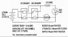
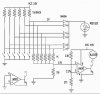
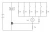
I need to design a circut which will be put into a cupboard with 6 drawers. If one drawer is pulled out, a red led should light up, if two are pulled out, a buzzer should buzz and the red led should light up.
Now comes the hard part") : this has to work with a battery at least 5 to 10 years...
: this has to work with a battery at least 5 to 10 years...
(by the way, this is to prevent the cupboard from falling over if too many drawers are open)
Thanx
pwollner
I need to design a circut which will be put into a cupboard with 6 drawers. If one drawer is pulled out, a red led should light up, if two are pulled out, a buzzer should buzz and the red led should light up.
Now comes the hard part
: this has to work with a battery at least 5 to 10 years...(by the way, this is to prevent the cupboard from falling over if too many drawers are open)
Thanx
pwollner