Continue to Site

Welcome to our site!

Electro Tech is an online community (with over 170,000 members) who enjoy talking about and building electronic circuits, projects and gadgets. To participate you need to register. Registration is free. Click here to register now.

  • Welcome to our site! Electro Tech is an online community (with over 170,000 members) who enjoy talking about and building electronic circuits, projects and gadgets. To participate you need to register. Registration is free. Click here to register now.

Need advice to convert a certain signal

Status
Not open for further replies.

mn1247

Member
Hi everyone,

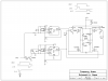
I need some advice. I have a DC signal that alternates between ground and Vcc at various times.

Each time it goes high, I need to generate a brief pulse. Likewise, when it goes low, I need to generate a similar pulse.

I'll try to diagram this...

Original signal:

......*************************************
......*........................................................*
......*........................................................*
****.........................................................********************

Desired output signal:

......****....................................................****
......*....*...................................................*....*
......*....*...................................................*....*
****......**********************************....*****************

The duration of the input pulse is from several seconds to minutes. The output pulses are about 0.5 seconds. Vcc is 9 VDC.

Also, I want to consume as little current as possible when the output is low.

Any advice on how to approach this conversion? Thanks

Eric
 
Last edited:
Achieving a single pulse when the input switches from ground to Vcc (or the other way) can be as simple as a capacitor and a resistor. Making multiple pulses requires a dozen parts or more.

Please tell about what is supplying the input changes, what the output needs to be compatible with, What is the least amount of response pulses you can allow, and such as that.
 
Brief pulse is what duration as in what is "brief"?

You could toggle a flip flop with your signal and have the alternate FF outputs drive a one shot like a 74123 or depending on the pulse width you want even a 556.

Ron
 
Have a look at this part. **broken link removed**
Use 1 half for positive edge detect and other half for negative edge detect and or the Q output. You can set pulse width using R and C.
 
The attached circuit should work, but it requires 5vdc not 9v.
 

Attachments

  • edgedetect.png
    edgedetect.png
    7.9 KB · Views: 186
Thank you for the circuit... that's a big help. Just wondering, in using the74LS123N, is it okay that the input pulsewidth is much longer than the desired output pulsewidth? I've heard that's not a good idea with the 555 and I'm wondering if it's an issue here. The input pulse is very long (seconds to minutes) while the desired output pulses (one at the start and one at the end of the input pulse) may only need to be 20 msec or so.

Again, Thank you.
Eric
 
Hi there,


How accurate do the output pulses have to be?

You might get away with two small NPN transistors and a few resistors and two capacitors.
 
Not very accurate... it will need to control a power transistor that will source 1.5A for 10-20msec (9 volts) to drive a latching solenoid.

Eric
 
Hi,


Do you have a certain technology you wish to use, or anything, or try to find simplest solution?
 
Thanks MrAl. I was able to come up with a pretty good solution (bipolar NPN) for the leading edge, but never was able to solve the falling edge.

I need low power and 9V operation... CMOS perhaps?

Eric
 
Hi again,


Oh yes CMOS would work quite well, perhaps that's the way to go.

The idea with the (two) transistors (however a third one is needed for inversion) or the CMOS is to first create a two phase clock, then use the falling (or leading) edges of both clocks to generate a pulse by routing each edge through a capacitor and into the next stage.

For example using one transistor set up to invert the input signal, the other two transistors would have their collectors tied together, and the input signal
would connect to a cap in series with the base of one of the two transistors, and the output of the inverter through a cap to the base of the other transistor.
The idea is that when either the input signal itself or the inverter output signal changes state a current pulse flows through one of the capacitors and turns one of the transistors on, but only for as long as the current pulse exists, and then the transistor turns off again. Since the two transistors are wire OR'd, either input edge causes an output pulse.

This might be easier to show using CMOS inverter (INV) gates:

Code:
IN o---+---INV----cap1---INV---+---o  OUT
       |                       |
       +----------cap2---INV---+
You should note however that there may be a few voltage protection diodes required and a couple resistors in series with the two caps. Also, the outputs of the two INV gates are wire OR'd.

You might want to try to come up with a complete working circuit yourself, but if not let me know and i'll post a schematic.
 
Last edited:
Latch

Mn,
I'm guessing you are still working the latching relay. It would help everyone if you could describe the whole project. Right now everyone is trying to make a single output pulse from each edge your input (which we don't know much about). Having said that I think something like this is what you are looking for. If you can't find the cmos 556 (low power)you need to add a cap on cv and on vcc.
PS. Are you are running this off a 9 volt battery? If so it won't run long.latch.GIF
 
Another way to do it: Drives a low resistance coil directly.
 

Attachments

  • DF39.png
    DF39.png
    43.9 KB · Views: 167
Thanks... you guys are awesome.

Okay, as requested, here's the "whole project"...

The finished unit will be a type of waterer for livestock. The front-end is an LED-photodiode detector unit that senses when an animal has entered the unit. I am basing this upon a project kit....

https://www.quasarelectronics.com/kit-files/electronic-kit/3130.pdf

I plan to remove the relay and tap that voltage to operate the pulse-generation circuitry (yet to be designed). (I will also be looking at reducing the power of this circuit - 45+mA is too much. Most of that is in the LED, but I don't need 15 meters distance (maybe 0.3m at most). So, I'm hoping a lower-power part will do.)

The "back-end" is a water valve controlled by a latching solenoid...

https://www.digcorp.com/assets/0000/0205/S305DC_ValveAdapter_catalogPG33.pdf

I am planning (unless there's a better way) to drive this using an SN754410 quad half-H.

Right now, I'm trying to figure out the best way to interface the "front" and "back". The front-end signal is either high or low depending on whether an animal is present. But, I need to convert this to two brief (maybe 20 msec) pulses to drive the SN754410 and solenoid. This saves power. The pulses can be fairly crude as to timing and waveform.

Yes, the finished product is intended to run on 9V batteries, so power is at a premium. But, the unit is only on during certain times of the day. I may try to have a recharger at some point.

Thanks for all your help on this.

Eric
 
Last edited:
Just to add to my last post...

I believe I will need to take the "front-end" signal ("FES") and convert it into three signals to drive the H-bridge:

1) An unchanged (carbon copy) of the FES that will go to input 1 of the SN754410
2) An inverted copy of the FES to go to input 2 of the SN754410
3) A signal consisting of brief positive pulses (20 msec) at the rising and falling edges of the FES to go to the "enable" input of the SN754410

I'm wondering how best to do this. Are discrete transistors the way to go? Or am I better off with CMOS 4000-series logic?

BTW, I have paralleled the two full H-bridges on the SN754410 to achieve higher max output current capacity.

MikeMI - Very clever circuit!
ronv - I'll look at the 556.

Thanks
Eric
 
Latching relay

I think the 754410 uses to much power for the battery so here is a desrete design that does't us much power. Just to make sure..... The animal sticks its head in and the water turns on. He (or she) :) backs out and the water turns off??
 

Attachments

  • latch2.PNG
    latch2.PNG
    103.3 KB · Views: 159
I think the 754410 uses to much power for the battery so here is a desrete design that does't us much power. Just to make sure..... The animal sticks its head in and the water turns on. He (or she) :) backs out and the water turns off??

Yep... you've got it.

Thanks for the circuit idea

eric
 
Status
Not open for further replies.

Latest threads

New Articles From Microcontroller Tips

Back
Top