Continue to Site

Welcome to our site!

Electro Tech is an online community (with over 170,000 members) who enjoy talking about and building electronic circuits, projects and gadgets. To participate you need to register. Registration is free. Click here to register now.

  • Welcome to our site! Electro Tech is an online community (with over 170,000 members) who enjoy talking about and building electronic circuits, projects and gadgets. To participate you need to register. Registration is free. Click here to register now.

Need advice on repairing a wireless speaker

Status
Not open for further replies.
Hi, I'm a novice electronics guy and I just blew my wireless speaker because I tried to do a simple repair to the DC input and bodged the polarity. The speaker system is: House of Marley Get Together Bluetooth Wireless Speaker

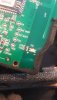
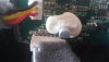
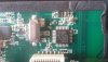
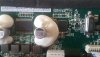
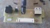
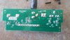
I can't find any schematics for it nor can I see any visible damage on the 2 boards.

I'm sure I shorted out something when I reversed the polarity on the power supply and am surprised that there was no diode to protect it.

As soon as I did the system died and will not work if plugged in (correctly) or on battery power so I'm sure the fault must be on the main board, not just the smaller PS board.

Any help would be greatly appreciated, even a link to a good replacement kit where I could reuse all the speaker & battery parts I have that Im sure are still good.
 

Attachments

  • 20181230_104618.jpg
    20181230_104618.jpg
    695.7 KB · Views: 282
  • 20181230_114912.jpg
    20181230_114912.jpg
    1.7 MB · Views: 312
  • 20181230_114935.jpg
    20181230_114935.jpg
    1.6 MB · Views: 248
  • 20181230_115004.jpg
    20181230_115004.jpg
    1.9 MB · Views: 273
  • 20181230_115014.jpg
    20181230_115014.jpg
    1.8 MB · Views: 253
  • 20181230_115054.jpg
    20181230_115054.jpg
    1.7 MB · Views: 259
  • 20181230_115102.jpg
    20181230_115102.jpg
    1.7 MB · Views: 251
Last edited:
There is some sort of switch-mode regulator on the main board. If you are lucky part of this will have failed and can be replaced. Check the components in that area.
If you can figure out where the power outputs from this circuit go you might be able substitute a stand-alone supply.
Possibly DC from the power jack/battery is supplying the output amp directly, I wouldn't like to guess, if so it's another place to look. The stuff in between is probably ok.

I thought about that but the fact that it won't power on via the battery (DC power unplugged) makes me think it must be more significant no ?
 
Welcome to ETO, B-in-N!

Sadly, my guess it that without any obvious diode protection, you've managed to cross polarize a lot of parts (especially µC's) that do not tolerate that situation at all. What that also means is that replacing SMD devices is probably well beyond your current level of expertise.

In short, toss the unit, get another one and learn from this particular mistake. If you stick with the hobby, this will just be your first mistake, trust me ... :banghead:
 
Last edited:
Welcome to ETO, B-in-N!

Sadly, my guess it that without any obvious diode protection, you've managed to cross polarize a lot of parts (especially micro C's) that do not tolerate that situation at all. What that also means is that replacing SMD devices is probably well beyond your current expertise.

In short, toss the unit, get another one and learn from this particular mistake. If you stick with the hobby, this will just be your first mistake, trust me ... !
Thanks, I think that's likely true but can't I do something like this with the parts ? --> https://medium.com/@kthornbloom/how-to-build-a-bluetooth-speaker-b145dd7475af
 
The battery will still go into the switch mode regulator. Sad to say Bob is most likely correct though.
 
Well, you've got a case with a speaker in it, a PSU which is probably pretty standard for a lot of things and a board to plug it into and take the power off elsewhere.
You could use the SMD parts off the main board for something if you have the skill to do so.
 
You can use a p-type mosfet backwards in series with the V+ line as an ideal diode. Connect the gate to 0v. It conducts through it's parasitic diode initially but immediately turns on so it's conducting through the channel. Good way of reverse polarity protection for low power equipment.
 
I damaged the power amplifier on a Bluetooth speaker set, when I was adding a rotary volume control, and the battery and speaker connections were the same type of plug.

I couldn't buy a replacement IC, so I got a different amplifier on a board from Ebay and used that instead.

You might find that the Bluetooth bit is still working and get a new amplifier, or you could probably get a Bluetooth receiver + amplifier and put that into the speaker housing.
 
If you can use a multimeter, you should check the connections if possible first. The easiest way is to power the device on and see to where does the current reach, but since your device does not power up, you will need to do more.

If you check which components are still working, you can use them as spare parts or in another DIY device.
 
Status
Not open for further replies.

Latest threads

New Articles From Microcontroller Tips

Back
Top