Continue to Site

Welcome to our site!

Electro Tech is an online community (with over 170,000 members) who enjoy talking about and building electronic circuits, projects and gadgets. To participate you need to register. Registration is free. Click here to register now.

  • Welcome to our site! Electro Tech is an online community (with over 170,000 members) who enjoy talking about and building electronic circuits, projects and gadgets. To participate you need to register. Registration is free. Click here to register now.

Need advice on hooking a Tach to my wind generator

Status
Not open for further replies.

KevinSB

New Member
Hi guys, this is my first post. I'm building a wind generator, and would like to monitor the RPM so I can compare it to wind speed and output. I tinker with electronics but am much more mechanically competent, so looking for some advice on the right way to do it.

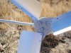
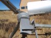
Here is the generator I'm using- **broken link removed**

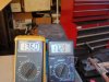
Here is the tach that I plan to use (already have one)- http://www.veeder-rootcounters.com/uploadedFiles/Downloads/MaxJrTachMan.pdf

I was thinking that it would be easiest to monitor 2 of the 3 legs before it is rectified to DC and calibrate the tach to read RPM. So, I think I need a circuit that can turn the variable voltage frequency into a pulse that is compatible with the tach. Voltage could potentially get over 100 VAC if the DC breaker trips in a storm and the generator has no load.

The simpler the better...any advice would be appreciated!

Kevin
 
Hi, and nice generator. That tach module accepts magnetic pickup input which is usually a large voltage range that outputs low AC voltage at low revs and high AC voltage pulses at high revs as typical with the older automotive magnetic sensors.

You should be able to just use 2 resistors as a voltage divider to reduce the generator AC voltage to safe levels and connect to that input of the tach module, the tach ground can be connected to battery ground.
 
Hi Kevin,
You dont say whether your building a VAWT or HAWT but that link does suggest a VAWT. Just be aware you'll need a pretty big swept area to gain any sort of power and dont expect too much power from a VAWT. On the graph to get 1kw the VAWT will need to be going at 450 rpm. Now that speed is damn scary and the generator support brackets and base pad will need to be rated for the thrust encountered at those speeds. The next hardest part is finding/making VAWT blades that can do that speed without flying apart.

Personally I'd make a output shaft with bearings and couple that to the generator and make a HAWT. They can easily do higher rpm's safely and with using a furling tail you'll have some protection from gale force winds.

As far as your tach goes, there are several inputs available, the logic output source would be the easiest way to input to the device. Simply a magnet and reed switch, power it with 5 volts and every rev will give a logic output.

Hope this helps

Regards Bryan
 
Thanks for the replies-
Mr RB- That sounds easy enough, I guess I would just start with high resistance values and then go down if it doesn't produce enough voltage to read at low RPM's? Any suggestion on values to start with? I bought the tach cheap a long time ago, but still would hate to burn it out.

bryan1- It will be the standard vertical shaft setup with about 9-1/2 foot diameter rotor and furling tail. The generator has a very strong shaft (I got the tapered one) and bearing setup, so blades will be mounted directly. The furling will be the hardest part to get right; probably like the Piggott setup for furling. I thought about just putting a barrel prox on it, but that's just another thing to go wrong 35 feet in the air, and more wire to run.

EDIT: Sorry, you guys probably think I'm an idiot, it's a HORIZONTAL shaft, not vertical :eek:
 
Last edited:
The automotive magnet/coil sensors I have worked with make an output sine-like wave from maybe 1v p/p at low revs to 50 volts or more at high revs. The input on your tach should be safe up to those sort of voltages. Usually they are capacitively coupled and they detect the transitions from +/- etc, so they are not voltage sensitive and are usually ok for highish AC voltages. But just to be sure I would play safe (as you said) start with maybe 10:1 voltage divider and see if it still works at low revs, then reduce the ratio so it works at even the lowest revs.

I'm not sure Bryan is right about reading the chart, the chart disclaimer says its for "fixed load" which was probably a resistive load. If that is the case and you fix it to a battery you will get higher output power at lower revs, it might give 1kW at much less than 400 rpm. Either way it does look high in the rpm, it needs 100rpm to start charging a 12v battery.
 
Hmm, according to the chart on the generator web page it won't reach 26v even at no-load until 200 RPM.

Will your rotor do 3.33 revs/second in a low wind allowing for some shaft drag?? (even at no-load there will be some shaft drag).
 
Hmm, according to the chart on the generator web page it won't reach 26v even at no-load until 200 RPM.

Will your rotor do 3.33 revs/second in a low wind allowing for some shaft drag?? (even at no-load there will be some shaft drag).

I don't know yet, but I think it will. I'm using aluminum blades similar to the ones made by TLG. I think their generator uses the GL-PMG-500 with about a 5' rotor, and they claim it's good for 24V charging. Mine will be the 1500 with a 9' rotor. I already built a smaller one with the same type of blades, and they're pretty fast in low wind. I plan to datalog wind speed, RPM, battery voltage, and generator current. I'll try it configured for 12 and 24V, then decide on which to go with before getting a larger inverter.

I attached a picture of my little one showing it charging about 17 A DC in decent wind. I didn't have my anemometer at that time, but I'd guess it was about 15 MPH.
 

Attachments

  • PB150027.JPG
    PB150027.JPG
    83.9 KB · Views: 938
  • PB150028.JPG
    PB150028.JPG
    81.8 KB · Views: 762
  • PB150030.JPG
    PB150030.JPG
    81.6 KB · Views: 559
Hi Kevin,
Nice pictures mate and thanks for showing them as it does clearup a few things. I thought you were making a Vertical Axis Wind turbine( VAWT) instead you pictures show a HAWT. Now 200 rpm cutin is a suitable speed for 24 volts as there should be some power in the wind to get them to that speed. Rather than spent a mint on Ali blades whynot get carving and make your own wooden blades, then as a learning experience you'll see how the blades perform and if they stall then going for a different Tip Speed Ratio (TSR) might be needed.

Regards Bryan
 
Thanks bryan1, I guess you read post#4 before I edited it. The 48" blades I bought on ebay were about $80 shipped, so that's cheaper than my time would be to carve my own, especially since I've never done it and and am too much of a perfectionist to make them in a reasonable amount of time. Maybe someday if I run out of other projects (not likely.) I'm pretty happy with how much torque and speed at low wind the old PVC pipe shape provides, although I don't have any "real" airfoil blades to compare them to. For now I need to spend my time getting the bigger one built with furling that works, putting up the tower, getting the control panel built with data acquisition, etc. After that, I can start playing with blade improvements. I'll post some more pictures as I get closer, but it's pretty slow-going. Too many hobbies..
 
but it's pretty slow-going. Too many hobbies..

Yea and that dam job seems to always waste most of persons day and week and year and lifetime! :(
Plus it often robs you of any ambition or enthusiasm towards anything when you do come home. :(
 
Status
Not open for further replies.

Latest threads

New Articles From Microcontroller Tips

Back
Top