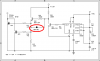
Continue to Site

Welcome to our site!

Electro Tech is an online community (with over 170,000 members) who enjoy talking about and building electronic circuits, projects and gadgets. To participate you need to register. Registration is free. Click here to register now.

  • Welcome to our site! Electro Tech is an online community (with over 170,000 members) who enjoy talking about and building electronic circuits, projects and gadgets. To participate you need to register. Registration is free. Click here to register now.

Need adjustable 15Khz Osc to drive ignition coil

Status
Not open for further replies.
F0rmatR said:
Well here we go.. attached is what I am working with. It uses a flyback to get the high voltage needed to produce ozone, 5KV approx at lowest setting.
As you can see it uses a motor speed control to change the output of the step down transformer. The 2k pot once set is not touched. By changing the values of R1 and R2, can we make this circuit get the same results by using an ignition coil instead of the flyback? I am thinking the mosfet won't handle the curent needed to get the ign. coil fired and there is not enough from the transformer to do the trick either.
This unit draws less than 1 amp. But will the ign. coil work?

hope i can attach a file. it is freehand but i think it will give you an idea what i am trying to do..

Yes, if the circuit works with flyback, it will work with ignition coils.

The main problem there is the frequency. Common ign. coils (the ferrosilicon core ones) do not have response on frequencies higher than 5kHz, 10kHz (maximum).

But if you adjust the frequency to a lower one, it will work.
Just some things I think:
1 - Supply the 555 with 5V, when I use the 555 with 12V it gets hot.
2 - You should take out that 110k resistor from PIN 5. (Does that have any purpose?)
3 - It's better to parallel 2 or more NTE2397, according to the datasheet it has 125W of power dissipation and it is not enough to run a ignition coil at 26V.
 
Hayato said:
Yes, if the circuit works with flyback, it will work with ignition coils.

The main problem there is the frequency. Common ign. coils (the ferrosilicon core ones) do not have response on frequencies higher than 5kHz, 10kHz (maximum).

But if you adjust the frequency to a lower one, it will work.
Just some things I think:
1 - Supply the 555 with 5V, when I use the 555 with 12V it gets hot.
2 - You should take out that 110k resistor from PIN 5. (Does that have any purpose?)
3 - It's better to parallel 2 or more NTE2397, according to the datasheet it has 125W of power dissipation and it is not enough to run a ignition coil at 26V.
Running the 555 at 5 volts will not provide enough gate voltage for the NTE2397.
 
Hayato said:
Yes, if the circuit works with flyback, it will work with ignition coils.

2 - You should take out that 110k resistor from PIN 5. (Does that have any purpose?)
3 - It's better to parallel 2 or more NTE2397, according to the datasheet it has 125W of power dissipation and it is not enough to run a ignition coil at 26V.

the 110k resistor?
from what i can tell this circuit HV output is controlled by adjusting the supply transformers input via a motor speed control. TRIAC. i may be mistaken but i think a TRIAC changes the frequency. so at pin 5 of the 555 we control the frequency going to it. the 110k resistor drops the current to it. so at max we will have 60 cycles - 26 volts. and at pin 3 of the 555 we would see somewhere around 19Khz. I didn't take my meter yet to check what the 2k pot is set at yet. i haven't taken my frequency counter to it yet either. but the way the circuit is right now it is working well. when i turn the motor speed control all the way down, there is very little ozone produced. when I turn the control all the way clockwise, it produces enough ozone for 1500 square feet.
The whole unit contains 2 transformers and 2 of these circuits and covers up to 3000 sq. ft. an ozone blaster. my gole is to make a smaller unit but to use a ignition instead of the flyback.
anyway i have messed with the math and i think i have the values to drop the frequency from 19khz to 8khz. by the look of the math you posted Hayato, it looks like you know what you are doing. so could you come up with some values for me to mess with. I will make the circuit up to the mosfet and test it. in the mean time i am going to hook up my meters to get some values of the voltage and frequency of the transformer and what effect it has on pin 5 and pin 3 of the 555.

Thanks for all the help so far..
 
Hello.
Take a look, it may be errors in there.

The 100k pot, will adjust the frequency of operation, from about 650 Hz to 23 kHz.
The 555 will output about 3.3V, like Ron H said before, it will not be enough to drive the power mosfets. But is enough to drive a BD139, so Q1 will act like a "voltage amplifier", and Q2 will act like a "current amplifier". (We are not interested in the linear region of the transistors, because we'll work with pulses.)

There is no problem to parallel mosfets (we do not need source resistors).

To obtain 12V and 5V from the 26V supply, just use the 7812 and 7805 ICs.

The main problem is that the duty cycle is not aways the same, it will vary from 45% to 67%. (Will vary as the potentiometer varies).

5552.gif
 
Can't view the pics

I have copied the pic to hard drive but can't read it. It is just a large blur when I try to enlarge it so I can view it. What program do you use to either uncompress it or view it?:confused:

Sorry got it Will view it and get back to you ASAP. Thanks again
 
F0rmatR said:
I have copied the pic to hard drive but can't read it. It is just a large blur when I try to enlarge it so I can view it. What program do you use to either uncompress it or view it?:confused:

Sorry got it Will view it and get back to you ASAP. Thanks again

Hello,
I'm using IrfanView, it's a very good one.
The picture is opening here, with IE and WindowsPictViewer.
I'll save as monochromatic BMP, zip it, and post it again.
View attachment schematics.zip
 
I suggest that you use a ignition module from a car! You will get a better spark Than any mosfet / transistor can do. and you wont have to worry about the duty cycle of the 555.
I made a spark simulator for an emmision testing machine ( I was not going to get burned anymore trying to reach down there connecting a pickup.)
 
Hayato said:
Hello.
Take a look, it may be errors in there.

The 100k pot, will adjust the frequency of operation, from about 650 Hz to 23 kHz.
The 555 will output about 3.3V, like Ron H said before, it will not be enough to drive the power mosfets. But is enough to drive a BD139, so Q1 will act like a "voltage amplifier", and Q2 will act like a "current amplifier". (We are not interested in the linear region of the transistors, because we'll work with pulses.)

There is no problem to parallel mosfets (we do not need source resistors).

To obtain 12V and 5V from the 26V supply, just use the 7812 and 7805 ICs.

The main problem is that the duty cycle is not aways the same, it will vary from 45% to 67%. (Will vary as the potentiometer varies).

View attachment 8610
I want to suggest a simple improvement. You will get faster turn-off of the MOSFETs if you add the diode, as below. Optionally, you could instead add a PNP follower for push-pull output, but the diode generally does a pretty good job.
 

Attachments

  • 5552 with diode.PNG
    5552 with diode.PNG
    18.5 KB · Views: 200
Ron H said:
I want to suggest a simple improvement. You will get faster turn-off of the MOSFETs if you add the diode, as below. Optionally, you could instead add a PNP follower for push-pull output, but the diode generally does a pretty good job.
Thanks Ron.
 
Status
Not open for further replies.

New Articles From Microcontroller Tips

Back
Top