Continue to Site

Welcome to our site!

Electro Tech is an online community (with over 170,000 members) who enjoy talking about and building electronic circuits, projects and gadgets. To participate you need to register. Registration is free. Click here to register now.

  • Welcome to our site! Electro Tech is an online community (with over 170,000 members) who enjoy talking about and building electronic circuits, projects and gadgets. To participate you need to register. Registration is free. Click here to register now.

Need adjustable 15Khz Osc to drive ignition coil

Status
Not open for further replies.

F0rmatR

New Member
I am having trouble comming up with an adjustable timer circuit that will osc at 15Khz. Well the biggest problem is the math for the RC. 50% duty cycle. It has been years that I have messed with these 555's and can't remember the math.
I will try to discribe what I already have:
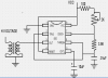
Pin 1 - Gnd
Pin 2 - 6
Pin 4 & 8 to plus voltage = VCC?
a 2.2K from Pin 7 to Pin 6
Pin 3 to a 22 ohm resistor with a 10K pull down resistor to ground driving the gate of a IRF740 MOSFET. Source to ground, Drain to an automotive 12V ignition coil.
Now from the adjustable power supply, (26VAC output, 110VAC input hooked to a fan speed control so to vary the trans output voltage). There is a full wave bridge and cap (220uF 50V) on the output of trans. 2 - 2K 1/2Watt resistors (1K) on the plus side to my 555. Now to vary the frequency a bit.
If I hook up a 2K pot from vcc to pin 7 what will I need for R Total?
There is also a 10uF cap on pin 5. There may be other parts of this circuit I don't need, so I guess what I am trying to do is vary the high voltage from the ignition coil from 6KV to say 10KV at 12Khz to 15Khz.
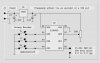
The circuit I have varies the output of a flyback transformer. I just need to make it work on an ignition coil.

I will stay tuned tomorrow for more info if needed.
Thanks.
 
Ozone Blaster

This is what I am trying to do with the above circuit -
I already have a Ozone blaster but it uses what looks like a flyback transformer to get the high voltage. I would like to make a smaller version of this but instead of a flyback I want to use an older car ignition coil. There is info on using this ignition coil on the internet, but it is not what I want. I need more control over the amount of ozone it makes. I need just enough to freshin the room, (low setting) to being able to blast the room. (1500 sq ft. high setting), for when I burn food when cooking.

I use to repair C.B. radios, but that was like 12 years ago. I use to build most of my test equipment as well. But that was then and I have fogotten just about everything and can't find books.

As soon as I get use to this site and how you share your pictures, I will post my findings.
Anyway I just need a bit of help getting the timing right. T=RC*1.1 = 15hz.
Thanks :confused:
 
Hello.
In some tests I've made, the ignition coils that use ferrosilicon plates core have an maximun oscillation response of about 4 kHz ~5kHz.

Look for a 555 Astable circuit to make the oscillator.
26V is too much, you'll burn the power transistors/mosfets.
I've burnt 3 paralleled 2N3055 with a 28V supply.
Try a lower voltage like 15V.
 
Hope this helps:
The ignition coil is a flyback transformer.
 

Attachments

  • HI VOLTAGE.png
    HI VOLTAGE.png
    16.4 KB · Views: 1,614
Hayato said:
Hello.
In some tests I've made, the ignition coils that use ferrosilicon plates core have an maximun oscillation response of about 4 kHz ~5kHz.

I am sorry Hayato, but lets look at a tipical 4 cyl, 4 stroke engine.
going down the road at 75MPH my engine is running at 3000 RPM's.
Now the math: coil has to fire 4 time per 2 turns of the crank. or 4*1500
already up to 6Khz. now what happens when I rev the engine to 7000RPM's?
7000/2*4=14Khz. what about the old 8 cyl engines @ 5000/2*8=20Khz

But who am i to argue? The 2N3055 Transistor? Great high power device.. but the circuit I am talking about is already working. I was just thinking all I needed to do was change the timing. If 4Khz to 5Khz works best on an ignition coil then I am game to try it. I need to know how to figure out the frequency. Could someone give me an example?
I will post the full diagram on this puppy once I get it running.

And thankyou Russlk, I didn't know this.
Hayato, you may find that the transistor you are using is your biggest problem. If you can get either the NTE 284 or a KSE13009, I think you will like your project a whole lot more..:D
Till next time.. thanks guys...
 
F0rmatR said:
I am sorry Hayato, but lets look at a tipical 4 cyl, 4 stroke engine.
going down the road at 75MPH my engine is running at 3000 RPM's.
Now the math: coil has to fire 4 time per 2 turns of the crank. or 4*1500
already up to 6Khz. now what happens when I rev the engine to 7000RPM's?
7000/2*4=14Khz. what about the old 8 cyl engines @ 5000/2*8=20Khz

A bit of a mix-up with units here.

4*1500RPM = 6000 cycles per minute, which is 100 cycles per second, (or 100hz in new money).

JimB
 
Thanks JimB.


F0rmatR said:
I am sorry Hayato, but lets look at a tipical 4 cyl, 4 stroke engine.
going down the road at 75MPH my engine is running at 3000 RPM's.
Now the math: coil has to fire 4 time per 2 turns of the crank. or 4*1500
already up to 6Khz. now what happens when I rev the engine to 7000RPM's?
7000/2*4=14Khz. what about the old 8 cyl engines @ 5000/2*8=20Khz

But who am i to argue? The 2N3055 Transistor? Great high power device.. but the circuit I am talking about is already working. I was just thinking all I needed to do was change the timing. If 4Khz to 5Khz works best on an ignition coil then I am game to try it. I need to know how to figure out the frequency. Could someone give me an example?
I will post the full diagram on this puppy once I get it running.

And thankyou Russlk, I didn't know this.
Hayato, you may find that the transistor you are using is your biggest problem. If you can get either the NTE 284 or a KSE13009, I think you will like your project a whole lot more..:D
Till next time.. thanks guys...

Well, about the 2N3055 circuit I forgot to mention I was driving a flyback transformer with modified primary, I've got about 0.2 Ohm in the primary side. :D

For classic Ignition Coils you have from 0.8 Ohm to 2 Ohms in the primary.
In my prototype I'm driving the coil with 2 2SC4106, salvaged from cheap computer PSU's.
With those transistors with much lower ratings than 2N3055 or NTE284, I'm able to run the coil for about 15 minutes at 5kHz.

2N3055 -> Ic = 15A, Power dissipation = 115W
NTE284 -> Ic = 16A, Power dissipation = 150W

2SC4106 -> Ic = 7A, Power dissipation = 75W

So I think I won't have problems by using 3 2N3055 paralleled. And, of course, I'll try the NTE284 or KSE13009, if I fail.

The formulae to get the spark rate is:
RPM = 120*SR/C
SR = Spark Rate in Hz.
C = # of cylinders.

That is, if you have 10000 RPM in a V8:
10000 = 120*SR/8
SR = 10000*8/120
SR =~ 667 Hz

Above 5kHz the coil doesn't spark very well.
Above 9kHz the coil doesn't spark at all.

What frequency you want to figure out? The optimun freq. for the coil? Well, you can try that:
When you turn on the device, start to change the oscilator frequency until you get longer sparks.

The longest the spark is, higher its voltage or higher its power.

Thanks.
 
"Russell, isn't the flyback voltage on the primary going to destroy the 555? "

Oops! I forgot that the flyback is not going to work because the 555 is always on. The 555 won't be destroyed, but the output will only be VCC times the turns ratio, which is probably about 100.

The high voltage MOSFET or IGBT will work, but the SCR won't turn off.
 
Russlk said:
"Russell, isn't the flyback voltage on the primary going to destroy the 555? "

Oops! I forgot that the flyback is not going to work because the 555 is always on. The 555 won't be destroyed, but the output will only be VCC times the turns ratio, which is probably about 100.

The high voltage MOSFET or IGBT will work, but the SCR won't turn off.

I think you forgot the power stage in your schematic.
The 555 outputs 200mA maximun, an ignition coil needs 6A ~ 18A to work well.
 
Russlk said:
"Russell, isn't the flyback voltage on the primary going to destroy the 555? "

Oops! I forgot that the flyback is not going to work because the 555 is always on. The 555 won't be destroyed, but the output will only be VCC times the turns ratio, which is probably about 100.

The high voltage MOSFET or IGBT will work, but the SCR won't turn off.
I think an SCR can be cap-coupled, or commutated off by another SCR. See my second reference in my previous post.
 
JimB said:
A bit of a mix-up with units here.

4*1500RPM = 6000 cycles per minute, which is 100 cycles per second, (or 100hz in new money).

JimB
whoops :eek:
Thanks JimB, my bad.. forgot cycles per second.... Sorry Hayato.

Ok I guess All I need now is the values for the 2 resistors, VCC to pin 7 and pin 7 to pin 6 and the cap value to give me the output frequency of 4Khz to 5Khz.
I would like to figure it out myself but I can't for the life of me remember how.
Is this right? = T=RC*1.1
and R has to be in megs and C has to be in.... in.... pF? or .000001 uF?
also there are 2 resistors to deal with. So is it something like this? - RA + RB * C * 1.1?
Help??? :confused:
Thanks to you all for the help so far. I have free hand drawing done up. I could scan it and let you guys tell me what you think of it if you would like.
Let me know.
ttfn
 
Ron H said:
I think an SCR can be cap-coupled, or commutated off by another SCR..
Thanks Ron H but I have that part covered. I am using an IRF740 with the output of the 555 through a 22 ohm resistor and a 10K pull down resistor on the gate.
The Drain of the MOSFET will be going to the primary of my coil.

ttfn
 
F0rmatR said:
whoops :eek:
Thanks JimB, my bad.. forgot cycles per second.... Sorry Hayato.

Ok I guess All I need now is the values for the 2 resistors, VCC to pin 7 and pin 7 to pin 6 and the cap value to give me the output frequency of 4Khz to 5Khz.
I would like to figure it out myself but I can't for the life of me remember how.
Is this right? = T=RC*1.1
and R has to be in megs and C has to be in.... in.... pF? or .000001 uF?
also there are 2 resistors to deal with. So is it something like this? - RA + RB * C * 1.1?
Help??? :confused:
Thanks to you all for the help so far. I have free hand drawing done up. I could scan it and let you guys tell me what you think of it if you would like.
Let me know.
ttfn

No problem.
Did you see that spark rate formulae there?

Ok, the 555 astable is given by R1, R2 and C1;
As you said:
VCC --- R1 --- PIN 7 --- R2 --- PIN 2 + 6 --- C1 --- GND.

Formulaes:
R1 and R2 = Ohms;
C1 = Farads;
T = seconds;
f = Hz;

T(high) = 0.696*(R1+R2)*C1
T(low) = 0.696*R2*C1

f = 1 / (T(high)+T(low));

f = 1.44 / ((R1+2*R2)*C1);

Duty Cycle must be different from 50%.

The main problem of this configuration is that the duty cycle is not fixed when you use a potentiometer to change de frequency.
 
I gave up using 555s long ago,if I need an oscillator I use an inverter with a resitor strapped across it and a cap from the input to ground. I you want to pulse the output stick a resitor in series with a diode across the other resistor and the ratio determines the pulse width. Push it through the other inverters in the package and drive some mosfets and you have a high power oscillator. If you're worried about the inverter not starting try using a schmitt
 
Hayato said:
Formulaes:
R1 and R2 = Ohms;
C1 = Farads;
T = seconds;
f = Hz;

T(high) = 0.696*(R1+R2)*C1
T(low) = 0.696*R2*C1

f = 1 / (T(high)+T(low));

f = 1.44 / ((R1+2*R2)*C1)
Oh boy... C1 = Farads? So a .01uF cap is 10^-6 or .00000001???:confused:
Also R1 = 2900 ohms and R2 = 2200 ohms. C1 = .01 uF

Help
 
F0rmatR said:
Oh boy... C1 = Farads? So a .01uF cap is 10^-6 or .00000001???:confused:
Also R1 = 2900 ohms and R2 = 2200 ohms. C1 = .01 uF

Help

0.01uF is 10nF so it's 10x10^-9 F or:
0.01uF = 1x10^-2 uF = 1x10^-2x10^-6 = 1x10^-8 = 10x10^-9 F

p = pico = x10^-12
n = nano = x10^-9
u = micro = x10^-6
m = mili = x10^-3
unit (Farad, Ohms...) = x10^0 = x1
k = kilo = x10^3
M = mega = x10^6
G = giga = x10^9
T = tera = x10^12

If you have R1 = 2900 Ohms and R2 = 2200 Ohms and C1 = 0.01uF

f = 1.44 / ((R1+2R2)*C1)
f = 1.44 / ((2900 + 2*2200)*10x10^-9)
f = 1.44 / ((7300)*10x10^-9)
f = 1.44 / (73000x10^-9)
f = ~ 1.97 x 10^-5 x 10^9
f = ~ 1.97 x 10^4 Hz
f = ~ 19.7 x 10^3 Hz =~ 19.7 kHz
 
I can't help thinking this would be a relatively easy microcontroller application. Approximately 15-KHz center frequency? 50% duty cycle and adjustable in approximately 100 to 200-Hz steps?

Regards, Mike

ionic-oscillator-jpg.8571
 

Attachments

  • Ionic Oscillator.JPG
    Ionic Oscillator.JPG
    30.9 KB · Views: 1,165
Change this to 4K - 5Khz to an ign. coil

Well here we go.. attached is what I am working with. It uses a flyback to get the high voltage needed to produce ozone, 5KV approx at lowest setting.
As you can see it uses a motor speed control to change the output of the step down transformer. The 2k pot once set is not touched. By changing the values of R1 and R2, can we make this circuit get the same results by using an ignition coil instead of the flyback? I am thinking the mosfet won't handle the curent needed to get the ign. coil fired and there is not enough from the transformer to do the trick either.
This unit draws less than 1 amp. But will the ign. coil work?

hope i can attach a file. it is freehand but i think it will give you an idea what i am trying to do..
 

Attachments

  • ozone1.png
    ozone1.png
    259.5 KB · Views: 748
Status
Not open for further replies.

Latest threads

Back
Top