Electro Tech is an online community (with over 170,000 members) who enjoy talking about and building electronic circuits, projects and gadgets. To participate you need to register. Registration is free. Click here to register now.
Welcome to our site! Electro Tech is an online community (with over 170,000 members) who enjoy talking about and building electronic circuits, projects and gadgets. To participate you need to register. Registration is free. Click here to register now.
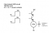
Hero, if you look at my statement on the drawing, is it a nand or a nor that I need?
1 + 1 = 0
1 + 0 = 0
0 + 1 = 0
0 + 0 = 1
I know I need base resistors and CEMF stuff, diagram is as simple as possible for demo purposes so I left a lot off, but I appreciate the warnings
Kinarfi
The diagram in my opening post would work as an AND circuit, being as the coil would energize with only with both inputs at 14 because of the orientation of the transistors.
Mikebits diagram would provide a NOR, but might not power the coil, depending on coil resistance, The diagram here would also act as a NOR by providing power for coil and closing the contact when both input are at 0
or at least, that's how I see it.
Thanks everyone,
Kinarfi
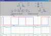
Because I like FETs so much, and have one that's good for a little over an amp, here's how I plan to do it after looking at all your suggestions.
Thanks for the help, greatly appreciated,
Kinarfi
Not an ignition coil, back when I learned electronics and then mixed it with PLC language, a circle is a common symbol for a relay coil and the contacts are as drawn for N.O. and with a diagonal line thru it for N.C. The circuit is correct and does work as intended. The contact is closed only when both OP-Amps have an out of 0
Kinarfi
This site uses cookies to help personalise content, tailor your experience and to keep you logged in if you register.
By continuing to use this site, you are consenting to our use of cookies.