Hey, I'm building a model of a construction crane. Using 3 Step motors, 3 step motor drivers and a microcontroller. Also 2 voltage regulators. Gonna use a joystick to control the step motors.
Well...anyway I'm wondering how the Step motor drivers work and where to connect the step motors. Since the step motors usually have 4 wires, (2 bright coloured and 2 dark coloured). But which output pins on the PDB??
Using following components:
3x step motors
3x PDB 3517 (www.isk.kth.se/kursinfo/6b2267/elmotorstyr/pbd3517/pbd3517.pdf )
PIC18F4431 (https://ww1.microchip.com/downloads/en/DeviceDoc/39616b.pdf)
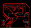
Here is what I've designed so far:
Well...anyway I'm wondering how the Step motor drivers work and where to connect the step motors. Since the step motors usually have 4 wires, (2 bright coloured and 2 dark coloured). But which output pins on the PDB??
Using following components:
3x step motors
3x PDB 3517 (www.isk.kth.se/kursinfo/6b2267/elmotorstyr/pbd3517/pbd3517.pdf )
PIC18F4431 (https://ww1.microchip.com/downloads/en/DeviceDoc/39616b.pdf)
Here is what I've designed so far: