Continue to Site

Welcome to our site!

Electro Tech is an online community (with over 170,000 members) who enjoy talking about and building electronic circuits, projects and gadgets. To participate you need to register. Registration is free. Click here to register now.

  • Welcome to our site! Electro Tech is an online community (with over 170,000 members) who enjoy talking about and building electronic circuits, projects and gadgets. To participate you need to register. Registration is free. Click here to register now.

need a little help here!

Status
Not open for further replies.
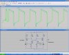
please help me with my project, Anyone who's familiar with this circuit, can you help me to know what watts is this resistor? the circuit is in the link below..
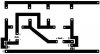
And can u help me to have the PCB design, I little unfamiliar with the connection of 3 feet of the transistor. How many transistor in this circuit?
Thanks!

hi,
There are 2 transistors in this Bistable circuit, all the same type, they are Darlington [ two transistors in one case.]

If you look at the inset diagram of the transistor you will see its marked C B E, these correspond to the circuit digarm C B E.

The wattage rating of the resistor, I would use either 0.125W or 0.25W whichever is handy.
OK.:)
EDIT: added d/s for the BD679
 

Attachments

  • datasheet.pdf
    115.5 KB · Views: 216
Last edited:
thank you sir, can I have a PCB design layout?
Is that wattage is for 12-volts sir?

The resitors will be OK at 0.125W or 0.25W.

If you go online and search for expresspcb its a free schematic and pcb layout program.
Its very easy to use, do a layout and post it, we will guide you thru it.:)
 
You should not use that simple circuit with a 12V supply. The max allowed reverse voltage for the emitter-base junction of the BD679 darlington transistors is 5V but with a 12V supply they will try to reach 11V and cause avalanche breakdown which is bad. The high avalanche breakdown current might cause the capacitors to blow up.

Use a 6V supply or add diodes to stop the avalanche breakdown.
 
Ceramic capacitors probably will not blow up but their small value will result in a fairly high frequency. The emitter-base junctions of the transistors will still have avalanche breakdown which is bad for them.
 
thank you sir, can I have a PCB design layout?
I wouldn't bother with a etched PCB for a simple project like this. Get a prototyping PCB with pre-etched tracks that you can cut with an exacto knife.
Also add the diodes as mentioned by AG:
 

Attachments

  • Beacon.gif
    Beacon.gif
    18.3 KB · Views: 195
No, you want the (-) side of the cap to go below ground when it's associated transistor turns on. Placing the diodes the way you suggested would result in high currents through the diodes and caps.
 
Sir, do I need to use 12 volt 100 microfarad for my capacitor? I used 16 volt 100microfarad capacitor and it blink a little and it stop.

0.125W or 0.25W can be used in 12 volts?
 
Last edited:
The capacitor charges to 10V or 11V so use 16V or 25V capacitors.

Calculate the power in the resistors. It is only 0.03W so any small resistors will be fine.

I don't know why your circuit stopped working. Maybe the polarity of the capacitors is backwards or maybe you connected the pins on the transistors backwards.
 
Good point about the high capacitance current with parallel diodes. The attached design uses resistors to limit the discharge current. The diodes clamp the reverse voltage across the BE junction of the transistor to less than 1V.

The problem I have with series diodes is that significant reverse voltage can still exist in the transistor's base, depending on relative reverse recovery times, leakage currents, etc. My design, although not commonly used, accurately controls the reverse voltage ( green trace in the waveform window ) The tradeoff is the limiting resistor must be carefully chosen to sustain oscillations. R7 would not be used in the acutal circuit. It's only included to get oscillations started in the simulation.
 

Attachments

  • astableMulti.JPG
    astableMulti.JPG
    130.5 KB · Views: 167
Last edited:
The high wattage rating of the resistor will not affect the operation of your circuit. 1/8 watt would be more appropriate however.

It might not be working due to the filiment bulbe used in the transistor collectors. You probably can't just plug any old bulb in to this circuit. That's a big weakness in this design.
 
Last edited:
The power rating of resistors is related to their size.
If they are still 4700 ohms then the circuit will work if everything else is correct.

But as I explained before, the circuit is wrong because it is missing two diodes.
Without the diodes then if the supply is more than 6V the transistors are damaged.
 
Ceramic capacitors probably will not blow up but their small value will result in a fairly high frequency. The emitter-base junctions of the transistors will still have avalanche breakdown which is bad for them.

sir what other resistor? In my circuit, I only have 2 resistor.
beacon-gif.33691
 
Each of the two 4k7 resistors is 4700 ohms. It can be a 1/4W resistor.
 
PCB layout

Sir, did I placed my diode and transistor correctly in my PCB layout?
Thanks sir!
 

Attachments

  • new theory PCB.JPG
    new theory PCB.JPG
    17.6 KB · Views: 161
Status
Not open for further replies.

Latest threads

New Articles From Microcontroller Tips

Back
Top