Continue to Site

Welcome to our site!

Electro Tech is an online community (with over 170,000 members) who enjoy talking about and building electronic circuits, projects and gadgets. To participate you need to register. Registration is free. Click here to register now.

  • Welcome to our site! Electro Tech is an online community (with over 170,000 members) who enjoy talking about and building electronic circuits, projects and gadgets. To participate you need to register. Registration is free. Click here to register now.

Need 1mA current source for testing LEDs (limited to 60V)

Status
Not open for further replies.

Flyback

Well-Known Member
Hello
We are using ten 34V CLU038 LED COBs on our mains connected product. We connect them as five lots of two-in-series. –So there are five connection wire pairs going off to them from the driver PCB.

CLU038 LED COB datasheet:
https://www.light.fi/assets/files/151210-CLU038-1206C4[Ra80-70]-DataSheet.pdf

Our assemblers unfortunately keep misconnecting them. Then when the whole luminaire is completely assembled, some or all of the five COB pairs don’t light up….
….We then have to spend ages disassembling the product so we can find out where the misconnection is and then correct it.
What we need is to test the LED COB pairs as they are assembled…to ensure they are correctly connected in.

So what we want is a 1mA current source with two probes so that we can touch the PCB pads to which the COB pairs should be connected, and check to see if the LEDs light up. Each COB pair needs about 59V to light up. We need the limitation to 1mA otherwise assembly staff may blind themselves.
We could make up a 1mA current source power supply ourselves, however, if there is something very cheap already available off-the-shelf, then we would prefer to use that. Does anyone know of such a product?
Do you agree that it’s not possible to electrocute yourself badly with 59V, with the 1mA limitation?

Also, supposing staff occasionally accidentally reverse bias the LEDs from time to time whilst testing them, do you agree that this could not cause damage to the LEDs? … because none of the individual LEDs within the COBs would get reverse biased by more than 4V, say. (the voltage would be limited to 60V)
 
So what we want is a 1mA current source with two probes
The easiest is probably a two transistor current source x such as this,
upload_2017-6-8_16-49-23.png

with a 60V supply.
The current limit is approximately 0.7V/Rsense so Rsense should be about 700Ω.
With a 1mA limit that should be quite safe.
Also, supposing staff occasionally accidentally reverse bias the LEDs from time to time whilst testing them, do you agree that this could not cause damage to the LEDs? … because none of the individual LEDs within the COBs would get reverse biased by more than 4V, say. (the voltage would be limited to 60V)
Not necessarily.
The reverse voltage will depend upon the reverse leakage current of each LED.
If one has a low reverse leakage current, the voltage across it could increase until it avalanches, which may damage the device
Would it be possible to add a small reverse diode (1N4148) across the string to carry the reverse current?
 
Would it be possible to add a small reverse diode (1N4148) across the string to carry the reverse current?
Thanks, great point, but no, ...but we will likely add that to the nexy PCB respin.

The reverse voltage will depend upon the reverse leakage current of each LED.
If one has a low reverse leakage current, the voltage across it could increase until it avalanches, which may damage the device.
Do you think that one of the LEDs could have that low reverse leakage current (compared to the others) that it would develop a reverse voltage of 7V, which would be enough to damage the LED? I mean, surely they would all have almost the same reverse leakage current? (as you know, i am referring to each of the leds in the COB....they are in fact connected 12_series, 6_parallel, so surely it would be inlikely that all 6 of the parallel connected LEDs would all have lower reverse leakage current than the other leds of the COB?)
 
Last edited:
..............
Do you think that one of the LEDs could have that low reverse leakage current (compared to the others) that it would develop a reverse voltage of 7V, which would be enough to damage the LED? I mean, surely they would all have almost the same reverse leakage current? (as you know, i am referring to each of the leds in the COB....they are in fact connected 12_series, 6_parallel, so surely it would be inlikely that all 6 of the parallel connected LEDs would all have lower reverse leakage current than the other leds of the COB?)
That's difficult to say offhand.
The spread in leakage current is generally not listed.
You could measure a bunch of them for reverse leakage and see what the scatter is.
But even a small difference in leakage can lead to a large difference in reverse voltage applied since the leakage tends to look like a constant current.
You may be okay, but it doesn't seem like good practice.
 
Do you agree that it’s not possible to electrocute yourself badly with 59V, with the 1mA limitation?
when i was younger and not so stupid i made a test powering me from the wall outlet of 220V~AC . . . yet another time i used a quanted potentiometer in series - a set of misc. kΩ - and a votmeter in parallel - so you start feel uncomfy from 40V~AC (Line to ground / "Earth" !!! not line to neutral !!!)
-- donno about DC
but being in series with with 82kΩ and -(±60V) neon tube you newer/barely notice touching the 180V~AC far off
-- from what i learned to sense active line with bare fingers !!! the point here is that the human's self-protecting reaction is to freeze at surprise - you must recode it for sensing the live line as to pull back your hand immediately and read the voltage presence at (blocked at the time of shock/sense "pre-buffer memory")
 
Do you agree that it’s not possible to electrocute yourself badly with 59V, with the 1mA limitation?
It may give you a bit of a tickle, I don't think that there will be scenes reminiscent of the film "The Green Mile".
However, the man from the HSE may not quite see it that way. I am sure that this busts one or two safety directives.

We then have to spend ages disassembling the product so we can find out where the misconnection is and then correct it.
In which case, why not perform a simple visual inspection before final assembly. The LEDs are clearly marked for polarity.

If you must do a power on test, build a test jig which will hold the assembly and apply power without anyone having to juggle around with "probes" which have 60 volts or so in them.

JimB
 
UL thinks that 32 Vdc or less is safe for direct contact, which is the S in SELV. They have separate rules for telecom voltages (up to 72 Vdc).

I agree with the instructed/tested/certified visual inspector approach. If you need to probe the assemblies, a jig would be better because if they couldn't get the LED orientation correct, how can you assume they will get the probe placement correct?

ak
 
I don't think 1ma, under any circumstances, can be lethal.
That usually requires at least 100mA.
 
Thnaks, i hear that the lethal amount is the amount which flows in a y capacitor of a typical domestic mains product...ie 250uA?...but thats at mains voltage...i hear at 60v and less it takes more current to kill. I think it depends if you touch hand to hand and it can go through the heart.
Of-the-shelf PSUs seem to be almost unavailable above 60V so i reckon the 60V level could be the lethal threshold?
 
i hear that the lethal amount is the amount which flows in a y capacitor of a typical domestic mains product...ie 250uA?..?
Depends on the application. For general purpose stuff (appliances, computers, etc.) UL60950 and 60335 limit the ground current to 3.5 mA (used to be 5 mA, maybe?). For medical equipment, UL 60601 has a much lower max current value, down around the 250 uA you mention. Patient-contact stuff is in a whole other category.

ak
 
i turned one of the wound transformers to 4x 24V~ that can be reconfigured also as above 60V DC when rectified to test diacs
so i forgot it's 60+ and got a sharp reminder -- as the aim of this work was not how scared one might get from -- i attempted further on not to get a hold on too great potential differences . . .

so it does definitely feel clearly ? make a mini conveyor that aligns led measures polarity if 90° error (no contact) rot 90 if 180 (wrong polarity) ? using legos ? maybe i'm day dreaming

some links (your ds doesnot spec. such narrow limits)
http://uv.chingtek.net/img_uv/LED_uv_K1_P007.jpg from http://uv.chingtek.net/products_08_3.htm
by google images x-target
 
Last edited:
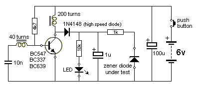
You need a little flyback inverter similar to the one I designed to test zener diodes. It works off a 9v battery.
 
Hi there,

The primary issue seems to be that of a current limit of some sort, but we can not depend on any current limit to protect us. Not 100ma, not 10ma, not 1ma. There are several reasons for this.
First, a current as little as 10ua can kill someone if it reaches the heart, and differing body conditions means it's hard to predict how and when that could happen.
Second, there are secondary issues that come up due to the human reaction to a non lethal shock such as a fall.
This means there should really be no shock ever, unless you like to gamble with someone else's well being.
Add to that 60v is certainly enough to kill someone. 1ma limit is nice, but may not always work.

One thing that is not usually mentioned is the time period required to kill someone with a variable current source. For the above example at 10ua, just how long would it have to be applied in order to kill someone even with low probability. Keep in mind that even a 0.1 percent probability kills on average 1 person out of every 1000 that are shocked. Certainly a shorter time period for the shock time would lower the probability, but i dont know of any such data being available. Also, it may never actually allow us to be certain that no one would ever be killed.

The bottom line then is that we want to reduce the probability of the chance of the shock itself, rather than try to lower the probability of a death by such a shock. And, we want to reduce that probability to zero.
The way to do this is to design the test equipment such that it can never deliver a shock to a person doing the test. A extreme example would be where the person connects the equipment, then has to reach outward left and right with both arms to push two different push switches that when both pushed at the same time initiates a test procedure for the equipment under test. The test is then performed automatically, which could take as little as 1 millisecond, the status then read off of some kind of display.

You can give this some thought. There are other problems that come up though for people doing tests that dont have any kind of technical background.
 
GFCI's typically trip at about 5mA so I would assume that any current below that is likely safe.
And that's for AC which generally causes death at a lower current than DC.

It's true a very small current through your heart can kill, but most of the current from a shock (even if from one arm to the other through you chest) does not go through the heart.

Hi,

Ok then lets pump 5ma through your body in 1000 different ways and see if you die. If you dont die, we'll do it that way :)

Alternately, you could donate funeral arrangement funds for anyone else that might die that gets 5ma through their body in the wrong way:)

Talk is cheap. If it was your daughter you might have a different opinion.
 
lets pump 5ma through your body in 1000 different ways and see if you die
Cute.
But we are talking about 1 mA here which is 1/5th of the 5mA GFCI limit.
However I guess your view is that any current through the body other than zero is potentially lethal. :eek:
 
i !guess! i never encountered the resistance below 20+smth. kΩ throughout all the occasions with multitude of multimeters and even then you have to press the sharp tips of the electrodes tightly against the skin so ... 65V–DC / 20k' = 3.25mA if there's a current limit you'll never get there . . . unless your supply leaks/trips to the ground ... or to the other potentials lying nearby with higher voltage values . . . so you may want to current limit both of your LED test leads and revese protect them (the operator) with high voltage FW diodes ??? -- i can't predict the effect(iveness) of such herein however . . . . . . make shure your current limit's won't start oscillating at "weird" loading
 
Cute.
But we are talking about 1 mA here which is 1/5th of the 5mA GFCI limit.
However I guess your view is that any current through the body other than zero is potentially lethal. :eek:

Hello again,

I like your view too though, about the 5ma limit on the GFI.
My view comes from a liability standpoint, where if it was my company i would be afraid of the lawsuits that may come of it, and there is also the secondary effects that could come up like a fall after the initial shock, even if the shock doesnt kill the person. If they get injured, it's can be pretty bad too in the courtroom :)

But yeah, it is interesting that they put a 5ma limit on the GFI's. They must have some faith in that. 5ma at 100v is 500mw, 5ma at 200v is 1 watt, enough power to raise the temperature of a 1 square inch surface area with convection air flow only by 60 degrees C. I guess it would have to be concentrated in the heart or brain. I dont know the path it would take either though, depending on how it entered the body. Some people get hit by lightning and survive, so it's a guessing game.
 
Status
Not open for further replies.

Latest threads

New Articles From Microcontroller Tips

Back
Top