My interest has been piqued by this thread.
NAVTEX, is transmitted on two frequencies 490kHz and 518kHz.
The signal is basically a 100bps teleprinter type signal. (no it does not use the old 5bit CCITT no2 code).
As I sit typing this, the receiver behind me is receiving data from Rogaland Radio near Stavanger in Norway.
The data is being displayed on a laptop computer running a bit of software called Frisnit.
Getting back to the receiver in the first post of this thread, I was confused as to how it worked.
It is basically a direct conversion receiver, basically a superhet where the intermediate frequency is zero, ie the conversion is straight from RF to AF.
The incoming 518kHz NAVTEX signal is is mixed with the local oscillator at 516.5kHz, to give an audio signal at 518 - 516.5 = 1.5kHz.
This audio signal is filtered by the op-amps and fed to the decoder.
( The little sketch of the filter passband shows the centre frequency to be 1.4kHz. )
Coming back to:
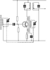
How should an ferrite rod antenna be connected to the diagram in my initlal post?
I would suggest like this:
The RF amplifier is a cascode circuit using FETs, so it is safe to assume the the input impedance will be high, so connecting the tuned circuit of the ferrite rod antenna directly to the gate of the FET will not result in any loading of the tuned circuit.
However, be aware that using the ferrite rod antenna on the bench with all sorts of other equipment could result in a lot of noise which swamps the wanted NAVTEX signal.
JimB

")

") . Or maybe that shopkeeper did.
. Or maybe that shopkeeper did.