Electro Tech is an online community (with over 170,000 members) who enjoy talking about and building electronic circuits, projects and gadgets. To participate you need to register. Registration is free. Click here to register now.
Welcome to our site! Electro Tech is an online community (with over 170,000 members) who enjoy talking about and building electronic circuits, projects and gadgets. To participate you need to register. Registration is free. Click here to register now.
I have to admit I cheated. I Googled "Mullard museum", but before I found one, I found **broken link removed**. Look in the lower right-hand corner. It's made by Telefunken, and it's the same part number.
I have to admit I cheated. I Googled "Mullard museum", but before I found one, I found **broken link removed**. Look in the lower right-hand corner. It's made by Telefunken, and it's the same part number.
You still win Ron, becuase I too tried to cheated and spent like 20 minutes looking at old tubes in a museum. Lots of old radios and weird tubes back then. That is why I through out x-ray and radio. hehehe..
But did not see that one for sure..
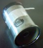
Wonder if you tune it with that tube stucking out of it.
The output was coupled to the waveguide by the "pipe" coming out of the mounting base.
The pipe is effectively a coax cable, if you look at the end you will see the last 8mm or so is the polythene dielectric with a centre core. This bit poked into the waveguide to couple the output from the klystron.
When I last played with one of these, they did drift about a bit compared with a Gunn diode.
Dag nabbit! Can't believe I got caught on that one... totally skipped past me. When it comes to Klystrons, I'm used to seeing these kinds inside the tower headends:
now THIS is a Klystron! **broken link removed**
BTW, JimB posted a pic of a "reflex" Klystron and the threaded rod is adjustable to move it's reflector.
I think I know what this is, but I will hold off for a while to give others a chance.
But first a few questions.
Is the bit in the left just a smaller version of the bit in the middle?
Does the bit in the middle fi t into the can on the right?
Is the can filled with some kind of fluid?
its a klystron
no,sorry,I skipped a couple of pages. That was the klystron that Ron identified. Its a microwave oscillator. The tube on the base is the output coupling probe. You tune it by turning the nut at the top and squeezing the cavity
OK, I'll post the same answer I PM'ed to you (and to JimB accidentally):
It's a combo bug zapper and hair spray.
Actually, it's a dummy load and wattmeter.
And I never saw one before - I just sleuthed it.
EDIT: There is no wattmeter. It's just a **broken link removed**. That box at the bottom of the page is apparently the wattmeter.
Yes, the one on the left is just an RF dummy load as far as I can tell.
The bit in the middle appears to have a few components fitted to make an RF power meter. The middle bit will fit into the can on the right, which is filled with oil to cool the resistor and dissipate the power.
This site uses cookies to help personalise content, tailor your experience and to keep you logged in if you register.
By continuing to use this site, you are consenting to our use of cookies.


")