Continue to Site

Welcome to our site!

Electro Tech is an online community (with over 170,000 members) who enjoy talking about and building electronic circuits, projects and gadgets. To participate you need to register. Registration is free. Click here to register now.

  • Welcome to our site! Electro Tech is an online community (with over 170,000 members) who enjoy talking about and building electronic circuits, projects and gadgets. To participate you need to register. Registration is free. Click here to register now.

My new oscilloscope

Status
Not open for further replies.

zachtheterrible

Active Member
I just got my new oscilloscope in the mail today and am extremely happy with it!

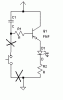
I have one question about it's behavior though. I made this circuit on a breadboard so that I could see the capacitor discharging. The probe was connected where the X's are.

The weird thing is that this circuit would work perfectly fine without the probe in there. When the probe was in there though, the LED would stay on just faintly. And even if the capacitor had drained all the way and the LED was off, if i stuck the probe in there, the LED would come back on faintly.

This only happens when the probe is connected to the scope, and it doesn't matter if the scope is on or off. The probe was in X1 mode.

Wuts a matta' here? Thanx :lol:

EDIT: I can't believe I forgot to attatch the schematic! I do that all the time.
 

Attachments

  • oscope.gif
    oscope.gif
    2.1 KB · Views: 765
Oscilloscope interfering with test circuit

Guessing at your circuit (no diagram attached)...

Is the LED driven by a transistor ? could you be picking up some mains (or other) interference that the transistor then amplifies ?

Is the 'scope lead's screen connected to a sensible point on your test circuit (negative power rail) ?
 
Hi Zach,
Congratulations on getting a 'scope. Now you can see how most electronic circuits work and don't work. Tell Mstechca how inexpensive it was and how valuable it is to see and understand circuits.

The input resistance of your new scope is a 1M resistor to ground, in parallel with about 100pF of its input and cable capacitance. The 1M resistor will mess-up circuits that use high resistor values and the capacitance will mess-up high frequency high resistance circuits.

A 10:1 probe has a 10M input resistance and much less capacitance. It would reduce but not eliminate your problem.

If your circuit operates at a frequency high enough (a few Hertz or more), use a low leakage coupling cap (poly film caps are very low leakage, electrolytics leak like mad) and if its value is high enough to pass the waveform without distortion then your circuit won't be loaded-down by the 'scope's 1M input resistance. With a coupling cap feeding it, the 'scope loses its ground and supply references so you must guess where they are on the screen.

I have used a coupling cap with my 'scope as I described, and temporarily speeded-up a slowly ramping circuit (by using a smaller cap in it) to be able to see its operation.
 
Quote Mechie

Trial and error is the best way of getting it wrong ?

Someone explain that to Mstecha!

Zack

Great to have a 'scope, it will help you see how circuits are or are not working.
But beware, as you have seen already, they can corrupt the operation of a working circuit, as can any piece of test equipment.

All my scope probes are x1/x10 switchable, and 99.9% of the time use them in x10 mode and do a mental calc to get the correct voltage.

When using x10 probes, DONT FORGET to adjust the frequency compensation trimmer. Otherwise you will get an incorrect voltage reading if the frequency is above a few hz.

For lots of good info about using oscilloscopes, have a look at the Tektronix website, www.tek.com.
They have a selection of "primers", one called "ABC of Probes" is quite good.

JimB
 
JimB said:
Quote Mechie

Trial and error is the best way of getting it wrong ?

Someone explain that to Mstecha!

He, he. :lol: :lol:
For certain he gets it wrong without having an inexpensive 'scope to see the results.
 
The circuit that I tested had a 12v supply. 12v through 1M=.0000012A. Definitely not enough to turn on my transistor to turn on the LED.

I attatched the schematic btw.

Is the LED driven by a transistor ? could you be picking up some mains (or other) interference that the transistor then amplifies ?
This is a possibility. When the scope is on 5mV setting, I see a sine wave that looks like it could be mains voltage.

Your oscilliscope is broken. Send it to me and I will dispose of it.
Do you know gullible is not in the dictionary?
 
Hi Zach,
The LED lights with or without the 'scope because the negative-biased base-emitter junction of your PNP transistor is avalanching.

Your circuit is supposed to have an NPN transistor! :lol:

If the avalanching didn't damage the PNP transistor then the circuit will work with it if you reverse the wires of the LED and connect a negative supply voltage at the arrow.
 
Your circuit is supposed to have an NPN transistor!
How in the world do you come to that conclusion Audio!?!? If it was an NPN transistor, how in the world would the base be positively biased??

When the NOPB switch is closed, the base becomes negatively biased through R1 as is customary for PNP's. Then the switch closes and the capacitor keeps that negative bias going for a little bit while it discharges.

I made two changes to the picture. GND is where I am connecting the oscilloscope's ground. I also put +12v where the positive supply of my circuit is. Maybe that's where you are confused Audio?
 
Hi Zach,
Swap the PNP transistor's collector and emitter and it will do what you want if its base-emitter junction isn't damaged by avalanching since it was connected backwards. The emitter of a PNP must always be positive to its base and collector voltages. You drew an emitter-follower and I thought that's what you wanted. I realize now that an emitter-follower doesn't have anything to provide base current except leakage current in the capacitor.

With its emitter at +12V, if the switch is closed then the base-emitter will be forward-biased and the transistor will turn on. R1 will have about 11.3V across it. When the switch is opened, the base-emitter current in R1 will discharge the capacitor until its charge is about 0.6V. :lol:
 

Attachments

  • oscope_corrected.gif
    oscope_corrected.gif
    2.6 KB · Views: 683
I'm sorry audio, I ALWAYS forget to mention that. I draw my schematics with switchercadIII and for some stupid reason, they have their PNP transistor backwards!!

I'll test out the interference theory when I go home, I'm at my cousin's house for the next day or two. The sine wave only appears when I have the hook attatchment connected to the oscilloscope probe, I'll try it without next time. The hook must be acting as an antenna.
 
Hi again,
Now that the PNP transistor is wired correctly (I suspect it was wired correctly but you simply drew it backwards), let's discuss the problem of the 'scope's 1M input resistance turning on the transistor.

1) Your calculation was incorrect, 12V across 1M is 12uA which is 0.000012A, not 1.2uA. Actually, it is 11.4uA less the voltage drop across R1.
2) The transistor is definately turned on a little since its base-emitter voltage is forward biased.
3) If the transistor has a current gain of 200, then its collector current is 2400uA, or 2.4mA which certainly will light an LED. :lol:
 
Hi again and again,
Zach I'm glad you connected the transistor correctly and it was just your drawing program that screwed-up! :lol:

The hook attachment makes a good antenna to pickup the 120VAC radiation all around you. That is why the probe's cable is shielded.
I have a powerful AM radio station about 5 miles from me and a couple inches of wire on my scope's probe picks it up. :lol:
 
audioguru said:
1) Your calculation was incorrect, 12V across 1M is 12uA which is 0.000012A, not 1.2uA. Actually, it is 11.4uA less the voltage drop across R1.
yeah, plus or minus a zero :lol: i did the calculation on my computer and must have forgotten to add the zero

Hmm, so it WAS the 1M input impedance. Wow, that can certainly screw things up. I guess that I will be using X10 from now on. I was under the impression that X1 was what I'd be using most.

Thank you for clearing this up everybody!
 
zachtheterrible said:
Hmm, so it WAS the 1M input impedance. Wow, that can certainly screw things up. I guess that I will be using X10 from now on. I was under the impression that X1 was what I'd be using most.

You probably will, you picked a REALLY SILLY example to start with, even a x10 probe will affect many circuits, you need to be aware of exactly what you are doing at all times (and why!).
 
Status
Not open for further replies.

Latest threads

New Articles From Microcontroller Tips

Back
Top