Continue to Site

Welcome to our site!

Electro Tech is an online community (with over 170,000 members) who enjoy talking about and building electronic circuits, projects and gadgets. To participate you need to register. Registration is free. Click here to register now.

  • Welcome to our site! Electro Tech is an online community (with over 170,000 members) who enjoy talking about and building electronic circuits, projects and gadgets. To participate you need to register. Registration is free. Click here to register now.

my circuit is getting crazy

Status
Not open for further replies.

mstechca

New Member
When I tested the radio with the push-button station changer (I also made myself) on a breadboard, everything works perfectly. HOWEVER, as soon as I turn the station-changing component into a PCB circuit, it doesn't work.

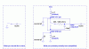
My station changer is basically a 4040 CMOS counter that uses 5 bits. The 1st bit gives output to 0.3pF capacitor (4 1.2pF's in series), the 2nd gives output to 0.6pF, and so on and so fourth. Bits 4 and 5 have outputs whose capacitors are wired in parallel. This circuit will give me a range of capacitance from about 0.3pF to about 9.3pF, enough for me to change stations.

All the connections are the same whether the circuit was on PCB or not, except that on the PCB, there were three wires (ground, +ve, and output to tank) about 1-2 cm long, and 1 (reset pin) about 5 cm long.

I would figure these wires shouldn't make much effect on the circuit with the exception of maybe 5Mhz down in frequency.

When I tested the PCB, the counter seems to work perfectly, and the resistors I used on the PCB are 27K resistors.

On the PCB, the circuit acts as if it was the antenna connected 2mm away from the +ve wire, but on the breadboard, it did not act this way.

Why doesn't it work now on the PCB?
 
that should have nothing to do with it.

Like I said, the whole thing worked on the breadboard, and my channel selector (before it was put on PCB) worked on the same breadboard as well.
 
maybe it only worked BECAUSE it was on a breadboard... if you tuned everything to work properly on a breadboard, where there's all that stray capacitance and inductance, and then moved it to a PCB where there's not nearly as much, everything's going to be different. much like if you randomly changed out components for different values.
 
mstechca said:
that should have nothing to do with it.

Like I said, the whole thing worked on the breadboard, and my channel selector (before it was put on PCB) worked on the same breadboard as well.
Below is an explanation of your tuning ckt as I understand your description of it.
The CD4040, in my opinion, won't really switch your tuning capacitor in and out of the circuit. It might change the inductance you have in series, which will probably be a lot different between the breadboard and the PC board, as Evandude pointed out.

Edit:
I reread your post. If you made the PCB look just like the BB, then parasitics may not be that much different. My comments about the effectiveness of the 4040 as an RF switch still stand. Note that the output is never high impedance.
 

Attachments

  • tuning_parasitics.gif
    tuning_parasitics.gif
    11.9 KB · Views: 984
Ron H said:
Below is an explanation of your tuning ckt as I understand your description of it.

The whole idea was pretty bizarre!, switching 0.5pF capacitors in a VHF tuning circuit using a CMOS logic chip?.

Incidently, a LONG time ago switched VHF tuners were quite common in the UK (in the valve days). The BBC radio stations (which were all there was back then!) all used a standard frequency shift between them - so you had a mechanical switch that switched in different capacitors, and a fine tuning control that selected where you were in the country. So you simply selected the lowest channel, adjusted the fine tuning for the lowest station, and the rest were automatically correct as you flicked the switch.

I always thought they were rather crude?, but they never gave any trouble, and the AFC had enough 'pull-in' range to make them work perfectly.
 
The left picture is the basic idea of my circuit. The right-most capacitor is the lowest (0.3pF), and each capacitor to the left of it is doubled (0.6, 1.2, 2.4, and so on).

The right picture shows what I would like to happen. Basically on the right, it would have been a rotary switch style circuit, but I don't like the rotary switch idea.

I managed to get the circuit working after I transferred the grounded inductor from the breadboard to the PCB.

But now, it seems that the steps are a little bit too small. I was expecting a 200Khz jump in each step, but it is more like maybe 50Khz or less.

I'll have to figure the whole superregen out. It either has to be the quench frequency I need to change or the base to ground capacitor. I'll have to look into it.
 

Attachments

  • pic_166.gif
    pic_166.gif
    2 KB · Views: 980
Nigel Goodwin said:
Ron H said:
Below is an explanation of your tuning ckt as I understand your description of it.

The whole idea was pretty bizarre!, switching 0.5pF capacitors in a VHF tuning circuit using a CMOS logic chip?.
Agreed. The simplest (and cheapest) RF switch that I know of is a PIN diode.
The simplest method of accomplishing electronic tuning would probably be to use varicaps (varactors) and D/A conversion.
 
Since I got something rolling, I'm not changing to varicaps and A/D design.

I think I'll have to play with my inductor to make the regen and the PCB happy :lol:
 
mstechca said:
Since I got something rolling, I'm not changing to varicaps and A/D design.

I think I'll have to play with my inductor to make the regen and the PCB happy :lol:
Please let us know when you get it working.
 
MStechca,
The outputs of a 4040 aren't a switch. They connect your capacitors all together. They are together because the outputs of a 4040 are either at the positive supply or at ground. The supply bypass capacitor in your circuit makes certain that the positive supply and ground are the same at RF.

Also, the outputs of the 4040 have an internal and wiring capacitance to ground of about 10pF on a pcb. Another reason why your little caps are all connected together.

Where in your super-regen circuit do you connect a capacitor to ground to change its RF frequency? Its antenna? :?: :?:
 
you can use your circuit to create different voltages (replace capacitors with resistor network or DAC). use this to control varicap diode. this is simple, clean and very popular.
 
audioguru said:
The outputs of a 4040 aren't a switch.
I know that. I was trying to avoid using manual switches and wanted to switch stations with the push of a button.

They connect your capacitors all together. They are together because the outputs of a 4040 are either at the positive supply or at ground. The supply bypass capacitor in your circuit makes certain that the positive supply and ground are the same at RF.

Also, the outputs of the 4040 have an internal and wiring capacitance to ground of about 10pF on a pcb. Another reason why your little caps are all connected together.

Where in your super-regen circuit do you connect a capacitor to ground to change its RF frequency? Its antenna? :?: :?:

At the emitter of the transistor where the tank circuit is.

I managed to get it working now after I stuck a 27K resistor between the chip's VCC and +ve.

Now I know my problem. My steps are too small. I must obtain larger value capacitors.
 
mstechca said:
audioguru said:
The outputs of a 4040 aren't a switch.
I know that. I was trying to avoid using manual switches and wanted to switch stations with the push of a button.
You don't understand that the outputs of the 4040 don't switch the capacitors in and out of the circuit. The capacitors are always switched into the circuit with the logic voltage changing at the 4040 end of each capacitor.

mstechca said:
audioguru said:
Where in your super-regen circuit do you connect a capacitor to ground to change its RF frequency? Its antenna? :?: :?:
At the emitter of the transistor where the tank circuit is.
The RF tank in a super-regen circuit is at the transistor's collector. The RF choke for the squegging blocking oscillator and the RF positive feedback capacitor is at the emitter. Unless you changed the whole circuit around again.
 
Audioguru, I'm not connecting the tank to the collector.
 
MStechca,
An RF tuned inductor/capacitor parallel circuit (tank) is a high impedance at its resonant frequency and matches the high impedance of a transistor's collector perfectly.

You have a high impedance tank at a low impedance emitter?
Then your circuit's tank tuning is squashed.
Then your circuit won't have any gain.
Then your circuit won't oscillate.
Then you don't have a super-regen tuner. :cry:
 
Status
Not open for further replies.

Latest threads

New Articles From Microcontroller Tips

Back
Top