Continue to Site

Welcome to our site!

Electro Tech is an online community (with over 170,000 members) who enjoy talking about and building electronic circuits, projects and gadgets. To participate you need to register. Registration is free. Click here to register now.

  • Welcome to our site! Electro Tech is an online community (with over 170,000 members) who enjoy talking about and building electronic circuits, projects and gadgets. To participate you need to register. Registration is free. Click here to register now.

My button works like magic, I only have to hover my finger over it

Status
Not open for further replies.
JustDIY; I tried a 1K resistor and it was better but not fixed. I had to touch the button (but not press it) to trigger.

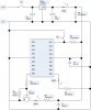
Mike; LVP is off in fuses, I attached 10K resistors between +5 and RB4 (LV PGM) and +5 and RA5 (MCLR). No change.

Philba; I measured the resistance with the power off it was 9.99K which is very close to the expected 10K. See above for the MCLR suggestion.

Nigel; I am charging the batteries for my camera.
 
Your code is fine. So it is likely that the pull up resistor or its connection is faulty in your initial setup.

To trouble shoot this situation, just connects a voltage meter to the PIC pin and watch. If your "magic hand" activates the PIC but the voltmeter reading shows no effect, you can then be absolutely sure that the signal is not "entered" via the PIC pin with pullup. You have other floating pins.

Edited: OP corrected coding error.
 
Last edited:
OK I have taken photos of the breadboard and had a go at drawing the circuit diagram. They are attached.

Most of the code and circuit diagrams are from Nigels Tutorial Site or Mike Predo's (spelling?) with my twist which is probably the reason for it not working.

I also tried the test elbc suggested however when the multimeter probes go anywhere near the pin in question it goes low, so my finger is not the only magic thing in the world.

:confused: :confused: :confused:
 

Attachments

  • StartGate1.asm
    8.5 KB · Views: 93
  • Breadboard.jpg
    Breadboard.jpg
    63.4 KB · Views: 147
  • Circuit Diag.jpg
    Circuit Diag.jpg
    90.3 KB · Views: 2,263
Try removing LED1 and R1, the Vdd pin of the microcontroller should be connected to the output of the voltag regulator.
In your schematic LED3 is backwards.
 
Yep the output of the regulator goes to the PICs VDD. Here's a typical hookup (it's missing the filter caps yours correctly has but does have the 0.1uf decoupling caps)
**broken link removed**
 
Last edited:
on your picture, you have the incoming power "POWER IN 9V AC" but on your diagram you label the power as "+12v" (ac or dc not specified)

feeding 9v ac into the regulator is going to make it rather hot, and should have blown out that big capacitor you have on the input

in the diagram, you show the LED being in series with the regulator, and a 330 ohm resistor connecting the positive rail to ground. On the breadboard, it appears the led and resistor are connected correctly, in parallel with the regulator.

On the PIC, Pin 4, RA5 / MCLR should be connected to the positive rail with a 10k resistor.

On the left side of the breadboard, there appears to be four wires leaving the circuit - where do these go? If I am to assume two of them are power coming in, and two of them are for the switch, I recommend moving the 0v (ground) connection from the incoming power directly to the ground terminal of the regulator, instead of having it travel around the entire breadboard before reaching the regulator. I also recommend installing a 0.1 to 0.33 uF capacitor at the input and output of the regulator.
 
justDIY said:
on your picture, you have the incoming power "POWER IN 9V AC" but on your diagram you label the power as "+12v" (ac or dc not specified)
My mistake it is a 12v DC supply (Transformer)

justDIY said:
in the diagram, you show the LED being in series with the regulator, and a 330 ohm resistor connecting the positive rail to ground. On the breadboard, it appears the led and resistor are connected correctly, in parallel with the regulator.
Does this mean I can leave it there? I want to see when I have power or not?

justDIY said:
On the PIC, Pin 4, RA5 / MCLR should be connected to the positive rail with a 10k resistor.
I have now done this, but I thought it was only required if the external MCLR is on in the config fuses in the asm code.

justDIY said:
On the left side of the breadboard, there appears to be four wires leaving the circuit - where do these go? If I am to assume two of them are power coming in, and two of them are for the switch, I recommend moving the 0v (ground) connection from the incoming power directly to the ground terminal of the regulator, instead of having it travel around the entire breadboard before reaching the regulator.
You are correct. I have moved the 0v wire.

justDIY said:
I also recommend installing a 0.1 to 0.33 uF capacitor at the input and output of the regulator.
This is where I need to do some more reading I think. Would these caps replace the ones I already have or be an addition? I do not understand the difference between 'Filters' and 'Decoupling Caps'. If in addtion where would I put them?

Thanks again for all your help. I am learning lots (although everyone seems to have a different way of doing things).
 
Last edited:
Well, you posted a schematic that is different from the actual circuit.

jimfraseruk said:
My mistake it is a 12v DC supply (Transformer)
Do you mean transformer with bridge rectifier and filter capacitor?


jimfraseruk said:
My mistake it is a 12v DC supply (Transformer)
Does this mean I can leave it there? I want to see when I have power or not?
You can use it beacase - as justDIY said - it's connected properly on the board.

jimfraseruk said:
I have now done this, but I thought it was only required if the external MCLR is on in the config fuses in the asm code.
If MCLR is disabled in fuses, don't use an external resistor.
 
eng1 said:
Well, you posted a schematic that is different from the actual circuit.

Do you mean transformer with bridge rectifier and filter capacitor?
Well it was my first attempt at a circuit diagram ;)

I have no what type of transformer it is, (maybe its not even a transformer)its a black box I plug into the wall, it takes in 220v AC and spits out a DC voltage of my selection (6, 9, 12, 15, 19, 24) upto 1.5A. It has no datasheet that I know of and its made in China.
 
proto boards like yours tend to suffer from poor connections, especially if they are old. I'd "buzz out" the connections - ie check continuity. Check the resistance between the PIC pins and where ever they are supposed to go. for example, check the input pin lead (RA1, not the resistor lead) and the +5 rail (not the resistor lead). Do so for all your pins.

Also, verify that you don't have bent pins on the PIC and make sure it is firmly seated.

Then power it up and verify voltages on the pins.

to your earlier question, you should be able to verify fuse settings in your programmer.
 
Try straddling the PIC with C3. ie: connect C3 as close to pins 5 & 14 of the PIC as possible. As Philba mentioned, use an ohm meter to make sure pin 18 of the PIC is really connected to R2 and that R2's other end is really connected to 5V.
EDIT:
I just looked at your code and noticed that w_temp and status_temp in the ISR are not saved in bank free memory. You should fix this so that w_temp and status_temp are in the 0x70-0x7F (bank free) range in case your main routine is interrupted while it is using banks other than 0.
 
Last edited:
Code:
loop
		call 	Check_Keys	; has start/ stop been triggered
		goto	loop		; Now wait for the next occurence.
		
;;;;;;;;;;;;;;;;;;;;;;;;;;;;;;;;;;;;;;;;;;;;;;;;;;;;;;;;;;;;;;;;;;;;;;;;;;;;;;;;;;;;;;;

Check_Keys
		btfsc	PORTA, BUT	; is there an input (low)
		call 	Send_StartStop	; Yes send start/stop signal to display
		return			; No do nothing

The "btfsc PORTA, BUT" in the code should be btfss.
 
Status
Not open for further replies.

Latest threads

New Articles From Microcontroller Tips

Back
Top