Finally, I has did it.
For those who've been following, this is the latest installment of my attempt to make a simple yet effective boost converter (3 volts--> 5 or 9 volts) using only discretes (only 3-legged parts allowed), kind of a poor man's version of the Minty Boost (a popular 5-volt boost converter built in a mint tin to power USB devices, for those who aren't familiar).
(By the way, I realize I have several other threads on this subject, but thought this was remarkable enough to warrant a new one. But if folks think I'm starting too many new threads with this, let me know; I don't want to be a thread polluter here.)
Previously I came up with a very workable 3-transistor boost converter design (regulated) that produced either 5 or 9 volts from 2 AA cells. I've built several of these and have been using them to power small projects that would normally use a 9-volt battery. (I say "I came up with", but must give credit where credit is due: I would never have made as much progress as I did without the help of others, particularly Mr. Al and Roman Black, one of whom supplied me the "power multivibrator" circuit.)
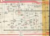
"My" design was one that I especially liked, since it was a mash-up of two classic circuits, a 2-transistor astable multivibrator and an inductor-based boost converter, using the second transistor both as part of the oscillator and the boost switch.
Problem is, that little BJT (a BC337) takes an awful beating in this application, and runs very hot, close to overheating. I tried replacing it with a small MOSFET, played around with a couple simulations in LTspice, but couldn't get anything to work.
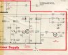
Well, tonight I sat down and took it up again in the simulator. After just a little tweaking, the thing started working incredibly well. The figures in the box at right tell the story:
**broken link removed**
So I'm happy to announce that at this point, at least in simulation, this thing beats the Minty Boost, and does it without any fancy-schmancy chips! Of course, this is just a friendly competition: I have no illusions about trying to usurp the people who produce that device. I just like the idea of being able to do this with readily-available parts a hobbyist might have lying around. The most "exotic" part, really, is the MOSFET, which I believe is available easily and cheaply from Digi-Key.
So far I haven't added my simple regulator (zener diode, another transistor tied to the gate), but don't anticipate any problems doing so. And I haven't yet checked this for efficiency; I'm very curious to see just how much of a drain this puts on those poor AA cells. But at least according to LTspice, it works like a charm. It's a little finicky: I could only get it to start at all by keeping the inductor within a very narrow range (about 8-10µH). This may just be an artifact of the simulator, and the real circuit might not be quite so demanding. Hopefully I'll be able to breadboard this soon.
Just did a quick efficiency check: not too good, only 52%. Some tweaking is needed here ...
So, any comments, advice or (constructive) criticism would be welcome. LTspice file attached below for you to play with.
Later: I added my simple regulator, which works flawlessly (gives 9.24V @ 92mA). LTspice file attached. At this low output, efficiency goes up to about 70%.
Hmm; efficiency goes up further, to 76%, when I increase the load by reducing RL to 50Ω.
For those who've been following, this is the latest installment of my attempt to make a simple yet effective boost converter (3 volts--> 5 or 9 volts) using only discretes (only 3-legged parts allowed), kind of a poor man's version of the Minty Boost (a popular 5-volt boost converter built in a mint tin to power USB devices, for those who aren't familiar).
(By the way, I realize I have several other threads on this subject, but thought this was remarkable enough to warrant a new one. But if folks think I'm starting too many new threads with this, let me know; I don't want to be a thread polluter here.)
Previously I came up with a very workable 3-transistor boost converter design (regulated) that produced either 5 or 9 volts from 2 AA cells. I've built several of these and have been using them to power small projects that would normally use a 9-volt battery. (I say "I came up with", but must give credit where credit is due: I would never have made as much progress as I did without the help of others, particularly Mr. Al and Roman Black, one of whom supplied me the "power multivibrator" circuit.)
"My" design was one that I especially liked, since it was a mash-up of two classic circuits, a 2-transistor astable multivibrator and an inductor-based boost converter, using the second transistor both as part of the oscillator and the boost switch.
Problem is, that little BJT (a BC337) takes an awful beating in this application, and runs very hot, close to overheating. I tried replacing it with a small MOSFET, played around with a couple simulations in LTspice, but couldn't get anything to work.
Well, tonight I sat down and took it up again in the simulator. After just a little tweaking, the thing started working incredibly well. The figures in the box at right tell the story:
**broken link removed**
So I'm happy to announce that at this point, at least in simulation, this thing beats the Minty Boost, and does it without any fancy-schmancy chips! Of course, this is just a friendly competition: I have no illusions about trying to usurp the people who produce that device. I just like the idea of being able to do this with readily-available parts a hobbyist might have lying around. The most "exotic" part, really, is the MOSFET, which I believe is available easily and cheaply from Digi-Key.
So far I haven't added my simple regulator (zener diode, another transistor tied to the gate), but don't anticipate any problems doing so. And I haven't yet checked this for efficiency; I'm very curious to see just how much of a drain this puts on those poor AA cells. But at least according to LTspice, it works like a charm. It's a little finicky: I could only get it to start at all by keeping the inductor within a very narrow range (about 8-10µH). This may just be an artifact of the simulator, and the real circuit might not be quite so demanding. Hopefully I'll be able to breadboard this soon.
Just did a quick efficiency check: not too good, only 52%. Some tweaking is needed here ...
So, any comments, advice or (constructive) criticism would be welcome. LTspice file attached below for you to play with.
Later: I added my simple regulator, which works flawlessly (gives 9.24V @ 92mA). LTspice file attached. At this low output, efficiency goes up to about 70%.
Hmm; efficiency goes up further, to 76%, when I increase the load by reducing RL to 50Ω.
Attachments
Last edited:

")
