Hi,
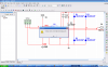
I have used Multisim before. You don't need a ground to the function generator as long as there is a ground in the schematic. This is the same for the oscilloscope.
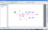
You can't use + and - of the function generator to test this schematic and it is also not needed.
Just connect one of the input to Vcc and you will see the motor turnning in one direction. Remove the Vcc from the input and connect to another input, you will see the motor running in another direction. Remember to connect the enable pin to Vcc.