Hello and thnx for the reply
I'm afraid your drawings (and conclusions) are somewhat meaningless if you don't include the important parameters and work through the math...
I dont quite agree with you here. No numbers are needed to show you my point of view! Even if more digits are added
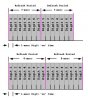
the time taken to refresh digit 1 (and every other digit) is not changing by the number of digits!. If the digit will be refreshed 10 times per second or 1000 timer per second has nothing to do with how many digits they are, but with how many time the refresh occurs.
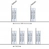
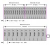
I've tried to make the drawing below similar to your Example A... In this case, yes, you could add a Digit 5 right behind Digit 4 and the display would have the same brightness... But that's because you left holes for extra digits within each Refresh Period...
As I realise it you dont want your mcontroller to be dedicated to the digits. The "holes" is the processing of whatever else the mcontroller has to do like drive motors, take measurement etc. However when the next refresh frame arrives, the mcontroller will refresh the digits again and go back to whatever is doing.
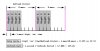
Now looking at your figures, i think understant our difference. You consider that between the refresh rates, ALL of the time should be used to light up the digits. Therefore the more the digits, less the time they will be light up hence less brightness. Hmm yes. I hope this is what you mean.
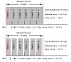
In any case, I considered that for each digit, a
constant amount of time should be spent, whatever the number of digits therefore is the refresh rate that makes the difference.
Thank you.
If this doesn't help, I promise to stop (grin)...
Why? We have a nice discussion here (more like you try to teach me something, but anyway :roll: )...
")