Continue to Site

Welcome to our site!

Electro Tech is an online community (with over 170,000 members) who enjoy talking about and building electronic circuits, projects and gadgets. To participate you need to register. Registration is free. Click here to register now.

  • Welcome to our site! Electro Tech is an online community (with over 170,000 members) who enjoy talking about and building electronic circuits, projects and gadgets. To participate you need to register. Registration is free. Click here to register now.

Multimeter problem

Status
Not open for further replies.

ngzek

Member
Multimeter DT9205A is giving continuous beeps and there is ligh in the led. Two probes are not touching. There is no visible burnt mark in the board. Please suggest which component should we test or replace. Please help
 
Normally, would this multimeter only beep when in continuity mode? If so, there might be something shorted or damaged in the continuity buzzer circuitry.

You will probably want to reverse engineer the circuitry to determine if it is handled through a separate circuit or through the main COB (Chip On Board) controller. You will likely need to look at both sides of the circuit board to do this, which will require taking the circuit board completely out of the case. If you do take the board completely out, depending on how the LCD is held in place, you will want to avoid damaging the LCD connections or disconnecting a zebra strip in a way that cannot be reassembled.

If the circuit is handled through a separate circuit, you will want to check for shorts or bad components in that circuit.

If it is handled through the COB and there is no other visible issue, then the COB may be damaged and you may need to replace that multimeter.

Are there any other functions on this meter that would cause it to beep? if so, you will want to check those as well.
 
Have you replace the 9v battery???

There is a topic here... https://www.electronicspoint.com/threads/multimeter-dt9205a-problem.269737/

Here is the schematics..
upload_2016-9-24_14-21-36.png

If you can find a buzzer on here let me know....
 
Nice find on the schematic. It didn't even occur to me to look for it. I agree, though, I can't find a buzzer or the LED anywhere. What is that thing in the top right marked A, B, and C with a crystal symbol? It seems to have no input to the main chip.
 
Okay, so I ran a text recognition on the Chinese cropped from that top right object in the schematic, and got this:

蜂鸣器 示意图

which, when plugged into google translate, reads: "A schematic view of the buzzer"

It seems fairly certain that that top right portion of the schematic is related to the buzzer. looking at the schematic, it seems like that would be a good place to start. I might start by checking the outputs at Q2 and IC4.

looking online, it seems there may be several different styles of DT9205A, so there may be multiple schematic and board revisions that might complicate things. That schematic seems to be for a version that has separate input slots for the capacitance tester, which not all versions of the DT9205A have. The OP will want to confirm that this version of the schematic matches up with his unit.
 
Yes we can see various versions in the market relating to this Model no DT9205A. The above schematics seems different from this board below. Thanks for your help.
 

Attachments

  • M2.JPG
    M2.JPG
    131.3 KB · Views: 1,248
  • M1.JPG
    M1.JPG
    175 KB · Views: 1,425
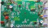
Hmm. It looks like most of the through hole components were hand-soldered, and they didn't clean off the flux at all. I would probably start by cleaning off the board with some rubbing alcohol and a cotton swab, then check for cracked or corroded solder joints.

If you aren't able to find anything obviously broken, then you will want to start tracing back the circuit to figure out what components are driving it. It's hard to make out the traces with all that gunk on the board, but it looks like that LM358 near the buzzer is a likely candidate. the left-side op-amp looks like it may be driving either the buzzer or the turn-off circuitry, probably in combination with those discrete transistors in the top corner. Once you have a basic schematic of the circuit, I would start checking the voltages and maybe some of those resistors.

After that, you would need to get into some real real nitty-gritty circuit debugging, so if the problem does not begin to manifest right away, you may consider getting a new meter before you sink an excessive amount of time into repairing this one.
 
Status
Not open for further replies.

Latest threads

New Articles From Microcontroller Tips

Back
Top