Continue to Site

Welcome to our site!

Electro Tech is an online community (with over 170,000 members) who enjoy talking about and building electronic circuits, projects and gadgets. To participate you need to register. Registration is free. Click here to register now.

  • Welcome to our site! Electro Tech is an online community (with over 170,000 members) who enjoy talking about and building electronic circuits, projects and gadgets. To participate you need to register. Registration is free. Click here to register now.

motor speed control

Status
Not open for further replies.

mccoy_tm

New Member
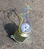
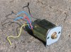
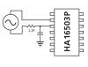
I'm modifying an old super 8 movie camera to have it's timing controlled by interfacing it with a microcontroller (ATmega168). I pulled the old motor out to figure out how it was originally wired. I've attached a couple of pictures of the motor. It's a dc motor powered by the red and black wires, the yellow wire is a ground to the case and the two blue wires come from a little alternator that piggybacks on the back end of the shaft and generates a frequency proportional to the shaft speed. I included a diagram of the way the alternator was wired to a chip on the control board. It was a Hitachi chip (HA16503P) but since it was made in the early 80's I can't find a data sheet on the web for it so I'm not sure what it is. I'm wondering if anyone has any thoughts on this. What I'm trying to do is convert the ac signal to a series of pulses that I can feed into the µcontroller. When the motor is running with no load at 9 volts the alternator outputs about 9.7 volts ac.

Thanks for any help.
 

Attachments

  • Motor_1.jpg
    Motor_1.jpg
    126.5 KB · Views: 379
  • Motor_2.jpg
    Motor_2.jpg
    173 KB · Views: 543
  • speed control.jpg
    speed control.jpg
    36.6 KB · Views: 324
Last edited:
Just connect it like the picture shows via a RC filter to the micro controller pin, but with the other side of the alternator to ground.

The microcontroller PIN protect diodes are good for 20mA so use a resistor that limits current to maybe 1mA or so, so try 9.7v-0.5v = 9.2v so try about 10k, but even 4k7 would be fine. The cap filters out any noise etc, use as large a cap as you can while still getting full scale 0v-5v swing at the micro pin at the HIGHEST motor speed. Try 0.1uF to start then tune it from there.
 
Last edited:
Thanks Mr. RB for your reply. I've never used a microcontroller before and don't have a lot of experience with electronics. I have to ask a few questions so that I can visualize what you are suggesting. I didn't realize that the io-pins had pin protect diodes so I looked them up in the µC data sheet to see if I could figure out how your suggestion would work.

If I wired the alternator to ground on one side and the io-pin on the other, I'm guessing it would result in a signal at the pin that would look like the output of a half wave rectifier? Is this correct?

During the top part of the wave the signal would pass unaffected as long as it didn't exceed Vcc. When the signal reversed you would forward bias the pin protect diode tied to ground and it would pass the current back to the alternator. Am I getting this right?

If this is the case and I'm getting a pulse at the pin, at what point along this analog "hump" will I transition to a logical 1 on the way up and then back to a logical 0 on the way down?

Wouldn't tying the alternator to ground introduce a fluctuation of voltage at ground that the voltage regulator would have to track to maintain Vcc at +5 volts. Would this cause problems with any internal reference voltages fed to the ADC's or analog comparator? If so is there any way to electrically isolate the alternator from the rest of the circuit?

Thanks.
 
...
If I wired the alternator to ground on one side and the io-pin on the other, I'm guessing it would result in a signal at the pin that would look like the output of a half wave rectifier? Is this correct?

You got it. These old type alternators as feedback generators on DC motors were common in mnay of the real old VCR's Betas, Umatics etc. Their AC voltage output is usually above logic level (ie > 5v) but low current and they were often fed direct to a logic level input on controller chips with just a resistor, cap, and of course the protection diodes.

As you said in the + phase the top pin diode will clamp it at just over 5v, usually about 5.5v.

During the top part of the wave the signal would pass unaffected as long as it didn't exceed Vcc. When the signal reversed you would forward bias the pin protect diode tied to ground and it would pass the current back to the alternator. Am I getting this right?

Yep. But remember the large series resistor 10k etc limits the load and hence the alternator current output, you want to keep the resistor large so it's just a voltage signal out, not extract any power from the motor. Those little alternator windings and tiny weak magnet would be lucky to put out more than a couple mA anyway even into a short.

If this is the case and I'm getting a pulse at the pin, at what point along this analog "hump" will I transition to a logical 1 on the way up and then back to a logical 0 on the way down?

Generally that will be at the threshold voltages of your digital pin, usually 1/3 and 2/3 of Vcc is typical. Either way it's irrelevant, you micro will time the period between / edges, which remains a constant threshold and can be used to calc the speed. Usually you will average a few periods anyway for stability.

Wouldn't tying the alternator to ground introduce a fluctuation of voltage at ground that the voltage regulator would have to track to maintain Vcc at +5 volts. Would this cause problems with any internal reference voltages fed to the ADC's or analog comparator? If so is there any way to electrically isolate the alternator from the rest of the circuit?

It's a valid point but most unlikely due to the alternator current being less than 1mA. In the - phase that current is just shorted via the 10k and diode, so it won't affect the PSU. In the + phase it *can* feed as much as 1mA back to the PSU but it would be most unlikely to affect the 5v rail unless your minimal consumption on the 5v rail during running operation was less than 1mA. Which I REALLY doubt since the purpose of this is an operating micro that drives a DC motor controller etc both of which would typically consume 5v at much more than 1mA.

If it bugs you then increase the 10k to 56k and use a slightly smaller cap. Or go for a higher parts count solution using a 4.6v or 5.1v zener on the input so it can't feed back to the PSU, or even use the + phase to turn on a NPN transistor and connect the collector of the transistor to your micro pin. The questions you are asking show you have a good knowlege of electronics and of the subtelties of the situation so I'm sure you can get it going. Anyway I really think you will be safe connecting the thing direct to the micro pin with just the resistor and cap. :)
 
RB,

wow, thanks for all the great information. This is my second post to this forum and I'm amazed at how much I've learned from just asking a few simple questions.

If the web was around when I first tried to teach myself about electronics back in the late 80's I might have kept at it. Thanks again.
 
Status
Not open for further replies.

Latest threads

New Articles From Microcontroller Tips

Back
Top