Continue to Site

Welcome to our site!

Electro Tech is an online community (with over 170,000 members) who enjoy talking about and building electronic circuits, projects and gadgets. To participate you need to register. Registration is free. Click here to register now.

  • Welcome to our site! Electro Tech is an online community (with over 170,000 members) who enjoy talking about and building electronic circuits, projects and gadgets. To participate you need to register. Registration is free. Click here to register now.

Motor field weaking

Status
Not open for further replies.

dr pepper

Well-Known Member
Most Helpful Member
One of the extruder motors where I work has failed, its a 500Kw Abb Dc motor.
I'm not very familiar with Dc motors & drives, very old hat, but this is what I have to work with.
I found a similar alternative motor, I'm going to have to make some mods to get it to fit, however the speed rating is a bit lower than what we need.
The suppliers have spec'd the job for me & said they can get the thing to run a bit quicker using field weakening, I've seen this before on Ac motors, weakening the field increases rotor current speeding the motor up till the rotor current balances again.
I'm not sure how this works in a Dc motor with field windings, probably very similar, there must be a limit where saturation or lack of repulsion takes effect, we only need 1950 rpm instead of 1800.
 
I don't see why it should not work. Assuming it is a shunt wound motor. If you consider the motor with no load on it the speed will increase until the armature voltage from the generator effect is equal to the supply voltage. (This is considering as a theoretically perfect motor.) If you weaken the magnetic field from the field coils the motor needs to spin faster to generate the same voltage. This will not be quite correct for a real motor as the current through the winding resistance of the armature will effectively reduce the supply voltage a bit. (Note I have never worked anything like that large.)

Les.
 
Field weakening was done all the time on such as older lathes with DC motor in order to get a slightly higher rpm at the sacrifice of torque.
Ensure however it has a field loss protection, otherwise if you lose the field supply while running it can run to destruction!
Max.
 
It sounds fine to me. Field weakening certainly speeds up motors. In this case it is only 8%. With a motor of that size, I would guess that the motor is run from a controlled bridge rectifier, so that armature current and motor speed can be controlled. If that is the case, weakening the field will reduce the torque and increase the top speed. If there is speed control with a tachogenerator, then separate field-loss protection isn't too important, because the supply voltage will be reduced to keep the speed constant. If there's no speed feedback, or the feedback uses the motor voltage somehow, then field loss protection is vital.

There will be a 17% increase in the centrifugal forces in the windings, but it would be highly unlikely that the physical strength is that close to the limit.
 
Its configured as shunt connected, we have to either reverse the polarity, or move the brushgear as off the shelf the motor goes the wrong way.
The motor armature is controlled by a thyristor Dc drive, there is tacho feedback, and all kinds of protection including power loss, overvoltage etc.
The field is a weird setup, the supply for the field comes off the 440v 3phase rail, through a trans down to 240v, then through a choke to 108v spec'd by the supplier (the rated field voltage is 155v, so theres a 47v drop in field supply), however this supply is monitored by the drive, both the voltage and current (via a ct) is monitored.
I'll mither the supplier about the 17% centrifugal loading, that occurred to me but I didnt think it'd be that much.
 
You will need to reverse the tacho generator as well as the armature.

I assume that there is a rectifier in the field winding supply somewhere.

What is the rated voltage for the field wind
 
Good call, I'm re-using the old tacho so the connections will be the same, however I plan to run the mot uncoupled to make sure of direction, I cannot risk going backards.

Yes the field has its own bridge rectifier, 2 of the diodes are scr's, the gates go to the drive, it controls the o/p, theres also a choke in series with the field, we have to replace this, as the field voltage/current isnt the same, the old motor has a 200v 24a field, the new is 155v 46a parallel connected 310v 23a series, our controls supplier has stated we should apply 108v to the field in parallel, one thing I'm trying to get an answer on is they implied the choke drops the voltage to 108v, however the rectifier is scr controlled so the drive will be able to regulate voltage, and would make more sense, sounds like the supplier doesnt know or has a lack of communication somewhere.
Not knowing the voltage or power factor involved I cant just do an inductive reactance calc on the field choke.
As per usual I end up waiting & being messed about by suppliers, the motor shows up tomoz, glad we only paid a deposit, also glad their commissioning engineer is signing the ticket after we've fitted it, however he'll need the correct stuff here & fitted before his bit can be done, yes I tried talking with this geyser but get the runaround every time and not got through.
 
Last edited:
Just remember that, the power (kW or HP) rating remains constant.

So if you run the motor a little faster than the nominal speed via field weakening, then your shaft torque will be lowered by the same amount.

Other than that, as Max has wisely advised, make sure that you have a field loss detector. Few things are scarier than a runaway DC motor!
 
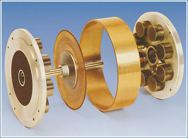
i worked for a company that repaired banking equipment, and one of the parts in a large machine that failed often, was a DC pancake motor, like the one in this picture
aufbau_ger.jpg


there are 8 pairs of cylindrical magnets arranged in a octagon shape inside the case, and the armature is a flat disc made of pcb material. the problem was that if the motor ran too hot, the cylindrical magnets would get weak. and in this motor, because there's no iron in the armature, would run the same speed, but with reduced torque, and in the machine it was in, if the motor stalled from low torque, there would be checks and deposit slips flung out of the front of the machine. it looked like one of those 1950's comedies where a computer gushed stacks of punchcards into the air...
 
I read up on it and get it now, generated back emf effect.
The motor has 2 independant overspeed detection methods thats not going to happen.
A runaway in this application would explode the motor through centrifugal means, the motor drives an extruder, the loading increases significantly with Rpm, the gearbox or screw would explode first, but thats bad, they are even more expensive and difficult to replace.
Found today that the mounts have been bodged numerous times, so I'm going to have to make & weld on some new mounts, at least it'll be on sunday pay.
And then theres a load of wires to connect, and a fan, even thats a great lump that'll need craning in.
 
Status
Not open for further replies.

Latest threads

New Articles From Microcontroller Tips

Back
Top