Continue to Site

Welcome to our site!

Electro Tech is an online community (with over 170,000 members) who enjoy talking about and building electronic circuits, projects and gadgets. To participate you need to register. Registration is free. Click here to register now.

  • Welcome to our site! Electro Tech is an online community (with over 170,000 members) who enjoy talking about and building electronic circuits, projects and gadgets. To participate you need to register. Registration is free. Click here to register now.

Motor direction

Status
Not open for further replies.

elfvenlord

New Member
Hi All

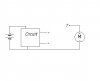
Im trying to build this simple project that requires a motor to rotate both ways.I know that to do that you would have to reverse the polarity to the motor(if thats how you say it).I only have one Battery connected to a circuit that switches two outputs on and off.

:?: Is there anyway to connect these two +V outputs to the motor so as to result in forwards and backwards.Check out the diagram below.
 

Attachments

  • motor_direction_496.jpg
    motor_direction_496.jpg
    8.8 KB · Views: 823
create a H-bridge out of MOSFETS
that way you can reverse teh polarity of the voltage (and thus the direction) and if you want to be really cleaver (you know you wanna) you can vary teh PWM feeding the switches and thus the average voltage going to the machine thus the speed can be changed

check out this

**broken link removed**
 
To change direction of a DC motor you must use bridge
type connection that allows polarity change.
The full bridge ("H bridge") is required for single power supply
while half bridge would do if you use dual power supply.
Since nobody likes to use dual power supply let's see the
full bridge example.
This can be done using relays as shown or making an
electronic version with transistors (there are specialized chips
for this of course). The advantage of electronic version is
faster switching time which is used to regulate the motor
speed by controling duty cycle (pulse width modulation).
 

Attachments

  • motor_632.gif
    motor_632.gif
    4.3 KB · Views: 829
Wow,Thats brilliant.Just read up about the H bridge and its perfect for what I need.

Its nice to know that theres an IC (L293) that does it all for you but I think I'd prefer to make the H bridge using transistors.That way I'll learn allot more.
Thanks guys for all your help,much appreciated. :D
 
One thing I have learned the hard way ( many FET's later ) is that if you do an H bridge for a single supply, design in switching for the FET's that makes it impossible to fire both FET's on either side simultaneously, or you short out the supply. Using FET's with built-in reverse diodes helps also. Most MosFets ar like this.

You can prevent the short out by using OR logic gates in the drive circuits or by using a bridge driving IC. You can get self limiting FET's ( current and temp ) that are logic level drive, something like a BUK102, or a VNP49n04 from ST Micro. They have good data sheets and design ideas also you may want to look into. i use the VNP's in a H bridge on 10 amp motors that reverse, and draw a stall current of nearly 50 amps, and have yet to smoke one of these FET's. I use a micro to control the switching.
 
zevon8 what you are talking about is a "shoot-through" and YES this must be prevented at all costs.

when you have designed your PWM logic to drive you will then have to manipulate it to ensure that you do not turn a top FET and a bottom FET (in teh same phase leg) on at teh same time.

If you number the FETS such

1 3
4 2

you will be sending PWM to say FET-1 and the inverse signal to FET-4
you NEVER want 1& 4 or 3 & 2 on at teh same time. Note there is a finite switching time with FET's so even if your logic signals show that 1&4 are never on at the same time, they might be comducting for a short period due to switching times.

The use of a OR gate and a NAND gate should create some interlocks.


Also you WILL need FET's with anti-parallel diodes, this is to allow teh current flowing in the machine (which is an inductor) somewhere to continue to flow when the switches are all opened. If you dont your FET's will blow up
 
Yeah I know what you guys mean about 'shooting through'
My circuit can only have one output at a time but it may change from one to the other in a few seconds,is that enough time to allow the transistors to switch off.Below is the circuit layout I want to build but I was wondering if it was possible to use all npn transistors or all n-channel MOSFETS.Cause surely the transistors act as a relay when they are saturated.

Also Im not too sure if the diodes should connect to the + and - of the motor,whereas they pass over it in the diagram ?
Sorry if the diagram is poor but I had to use paint. :lol:
 

Attachments

  • h_bridge.jpg
    h_bridge.jpg
    17.2 KB · Views: 731
good that you appreaciate the problems of shoot-through
here is a piccy of a 6 switch IGBT module in a 3ph arrangement. It is a 1200V 150A module
we had a problem with the FPGA code on our 7channel gateboard and it turned on all 7IGBT's on a 270V link with 500uF of capacitance

**broken link removed**


as to using all N-tpye devices you can but you will need to provide a isolated supply to drive teh top two FET's since if you look at it as the drive is switching you will be passing current into teh motor winding the source voltage of teh upper FET's will be jumping around thus you cannot ensure that you will be saturating the FET's

either using a floating/isolated supply for the top two, or if your link voltage is low enough w.r.t. your control votages use P-types


as to your diode question. All diodes MUST be facing up in your present arrancement ie the cathodes all pointing to teh +ve rail
 
Ah right, I drew the diodes the wrong way.Yip so they all face upwards.
I think I'll just stick to using p channel MOSFET's for the top two transistors.

Is there any chance someone could give me a link or a quick explanation about p channel MOSFET's.I had a look on the net but wasn't too succesful.

From my knowledge (shortest book ever written) of p channel MOSFET's,the less the voltage at the gate,the greater the current through the transistor.So if the gate voltage is at say 0V, then the transistor is saturated.Am I correct?

Sorry to Drag this on Guys. :wink:
 
P-type are easy to follow.

Think of them as backwards N-type.
Current flows through them the other way

To turn on a N-type you bring the Gate-Source voltage above a threshold
To turn on a P-type the source-gate voltage must be below the threshold.

To turn on a N-type charge must be pumped into the gate region
To turn off a P-tpye charge must be drawn out of the gate region


so if your battery is 15V if you supply 15V to the N-type it will turn-on and a P-type would turn-off

supply 0V and the N-type will turn-off and the P-type will turn-on

this effect simplifies drive cct that have a P-N phase leg since just a single signal need to be sent (no extra inversion), however since no extra inversion is needed it can be easy to forget abt interlocks to stop shoot-throughs
 
OFFLINE UPS

i've college assignment to design OFFLINE UPS. Unfortunately we dont have good guidence at college. I'm also eltrx newbie in design.

Plz Suggest some links. Also guide me step by step how to proceed.

Specifications:
1) 500VA
2) o/p= 230 V quassi-square
3) battery:24V, 7.5A backup time: 30 mins.
(from this we can get VA and AHr. rating of battery)

Features/Indicators:
1) Charging
2) Battery starts trickling
3) overload trip indicator (with time condn, should not trip immediately, wait few seconds)

4)MOSFET f/b isolation (whats this ??? :?: )

Plz reply back.
regards,
Neil.
 
Sorry, by mistake i placed it under reply instead of new top

OFFLINE UPS
Sorry, by mistake i placed it under reply instead of new topic.
sorry, Neil.
 
Thanks styx.
I've got it now.Out of interest is it similar to a pnp BJT,where it switches if current is through the collecter and base i.e. base is at 0V.
 
Status
Not open for further replies.

New Articles From Microcontroller Tips

Back
Top