Continue to Site

Welcome to our site!

Electro Tech is an online community (with over 170,000 members) who enjoy talking about and building electronic circuits, projects and gadgets. To participate you need to register. Registration is free. Click here to register now.

  • Welcome to our site! Electro Tech is an online community (with over 170,000 members) who enjoy talking about and building electronic circuits, projects and gadgets. To participate you need to register. Registration is free. Click here to register now.

mosfets are hot when 7.2V is used instead of 5V

Status
Not open for further replies.

mik3ca

Member
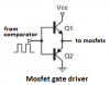
This is the circuit I'm using to add power to my speaker. The comparator output is connected to an output of an LM393 and its inputs are connected to a 555 timer and input audio which in my case is the analog output of a ISD1760PY chipcorder.

When I make +V equal to the regulated 5V (using an LM2940 regulator), nothing heats up and I get the correct sound when I make the rest of my complex circuit play it and everything seems normal.

The only issue I have is volume. I wanted to try to make the thing louder. Someone said volume of sound is based on amplitude and amplitude is based on voltage and someone said that when working wirh mosfets that I should use higher than 5V as 5V is the bare minimum turn-on voltage?

Nevertheless, I decided to connect +V directly to +7.2V from the battery instead of the regulated 5V output. At first everything worked well but after about a minute I smelled something strange and after touching the tips of the mosfets, they were HOT. Luckily, I made +V 5V again and things worked like before (without extra volume).

I guess these mosfets have some overvoltage protection in them?

But my question is why would they heat up so much if the voltage is only a maximum of 2.2V over?


circuit.png
 
I'm just going to use resistance as an example instead of inductance or capacitance because it's simpler but I think it should demonstrate the point:

V = IR and P = V^2/R = I^2*R

44% more voltage = 44% more current = 107% more power dissipated in the on-resistance of the MOSFET.

"Only" 2.2V is not a small fraction of 5V. It's quite large.

Also, those MOSFETs seem to be intended to run at a gate voltage of 10V, not 5V. The gate threshold says they turn on at 4V, but that's the threshold. The rated on-resistance is given at 10V.
 
Last edited:
Lets see... For 5v....

I=V/R = 5/680 = 7.35mA
P=I*V = 36.7mW

For 7.2v...

I=V/R = 5/680 = 10.58mA
P=I*V = 76.2mW

Ok so my calculations agree with your theory but How is it possible for 76.2mW to overheat something? that doesn't even heat up a 1 cent 1/4 watt resistor. unless I'm using the wrong resistance in my math?
Power dissipated alone is not representative of the temperature of a package. You need to look at the junction to ambient thermal resistance of the package.

Your math is also wrong. You are choosing all the wrong values. Why are you using 680 ohms? That's your gate resistor and the gate resistance is near infinite.

You go P = IV = Ids * Vds OR Ids^2 x Rds OR Vds^2/Rds.

The Vds is the voltage drop across the MOSFET when it's conducting, not the supply voltage. Ids is determined by the impedance of LC and the frequency.

Since it's an LC circuit it's probably just easier to measure the Vds and Ids rather than trying to determine the resistance Rds through direct measurement or trying to determine the impedance of the LC, through eithermeasurement or calculation, in order to find Ids.

Datasheet says that the IRF520 heats up 62C/W and the IRF9350 heats up 40C/W.

60C is what is perceived as too hot to touch for most people.

Increase the gate voltage to 10V so your MOSFETs actually turn on all the way. Your problem might go away.
 
Last edited:
Also, why are you calculating the power in the 680Ω resistor?

Mike.
 
Also, why are you calculating the power in the 680Ω resistor?

I figured that was the resistor that controls current to the mosfets? I guess not.

Increase the gate voltage to 10V so your MOSFETs actually turn on all the way. Your problem might go away.

I already made the PCB and if you're suggesting increasing gate voltage, then that increases gate current. wouldn't a lower resistor produce the same effect? and here i was thinking of raising the resistor value. I'm confused.


Power dissipated alone is not representative of the temperature of a package. You need to look at the junction to ambient thermal resistance of the package.
I'm used to working with BJT transistors not mosfets, but I'm only using mosfets to create additional amplifier gain.

Why are you using 680 ohms? That's your gate resistor and the gate resistance is near infinite.
I'm using the output of the LM393 comparator to drive the gates of the mosfets, but the output of that comparator is open-collector so I figured a decent resistor is necessary to at least make the comparator function.

You go P = IV = Ids * Vds OR Ids^2 x Rds OR Vds^2/Rds.

The Vds is the voltage drop across the MOSFET when it's conducting, not the supply voltage. Ids is determined by the impedance of LC and the frequency.

Which LC circuit? the one connected to the speaker?

So I have to calculate the frequency (1/2*pi*square-root(lc)) then calculate the impedance of each part based on that frequency and add the two impedances together to form the resistance I need to calculate for? or am I still confused?
 
I figured that was the resistor that controls current to the mosfets? I guess not.
It is, but you were trying to determine how much heat was dissipated in the MOSFET which is different than the thing controlling it.


I already made the PCB and if you're suggesting increasing gate voltage, then that increases gate current. wouldn't a lower resistor produce the same effect? and here i was thinking of raising the resistor value. I'm confused.
Think of a MOSFET gate as a capacitor. Once the capacitor gets past a certain voltage, the MOSFET turns in and as the voltage gets higher, the MOSFET turns on even more.

More current just changes how fast the MOSFET turns on and off. Like a capacitor, once the gate capacitor fully charges, no more current flows. This is different than a BJT.

How much the MOSFET turns on is controlled by the voltage. How fast it turns on is controlled by the gate current. Two different, independent things. Reducing the resistor will make the MOSFET turn on and off faster but won't make it turn on more (that is controlled by the voltage).

How much current flows through a MOSFET is determined by the VOLTAGE at the gate, not the current going into it. This is different than a BJT,

Which LC circuit? the one connected to the speaker?
The entire load. so the both LCs and the speaker.

Since the MOSFET is supposed to be a very low resistance when it is turned on (if you are turning it on sufficiently which is in question right now), then the impedane of the LCs and the speaker will determine how much current passes through the MOSFET.

So I have to calculate the frequency (1/2*pi*square-root(lc)) then calculate the impedance of each part based on that frequency and add the two impedances together to form the resistance I need to calculate for? or am I still confused?
That would work

Using the frequency of your square wave will give you a rough estimate (technically there are higher frequencies in a square wave and it will throw your numbers off but should be good enough for an estimate of the minimum current).
 
Last edited:
So I guess I should raise the resistor to 1K? and raise the capacitor and inductor values if I make V+ as 7.2v? The square wave frequency is between 100kHz and 1mHz (driven by a 555 timer) but that is also mixed in with incoming audio? but then maybe replacing inductors with resistors might work better (to reduce heat) but then what would be my drawbacks then?
 
So I guess I should raise the resistor to 1K? and raise the capacitor and inductor values if I make V+ as 7.2v? The square wave frequency is between 100kHz and 1mHz (driven by a 555 timer) but that is also mixed in with incoming audio? but then maybe replacing inductors with resistors might work better (to reduce heat) but then what would be my drawbacks then?
No, increasing the gate resistor won't do anything. The problem could be just that your gate drive voltage is not high enough. You are barely above the threshold votlage where the MOSFETs turn on right now.

I would change the MOSFETs if you can't modify the PCB. Get logic level MOSFETs (MOSFETs with a rated on-resistance at 5V or less). You are also using 400V MOSFETs so they are a lot higher resistance then they need to be (it doesn't seem to me like you are doing anything anywhere near 400V.

Even more importantly, you would blow your PMOS anyways if your +V is larger than 20V because the maxmimum gate-source voltage on the IRF9350 is 20V and you will apply +V and GND across the gate-source every time you pull the gate low to turn it off. Your circuit is being limited by the gate-source voltage of your PMOS, not the source-drain voltage of any of your MOSFETs.

Simply pulling a high-side PMOS gate low has this weakness in that the max gate-source voltage is the limiting factor, not the source-drain voltage.
 
Last edited:
If your Mosfets turn on perfectly with no voltage drop then with the supply of 7.2V the signal to the speaker is 7.2V p-p which is 2.5V RMS. Then the power in the tiny AL30P 8 ohm speaker is only 0.8W when at full blast but the average will be only about 0.08W. The tiny speaker is too small to produce low frequencies and its output level is fairly low for other frequencies.
You would get 3.5 times more power from a modern class-D bridged amplifier module.
 
The datasheet for the LM393 comparator says that its max saturation voltage is 400mV when its output current is only 4mA but the 680 ohm collector pullup resistor has a voltage of 2.7V across it when its current is 4mA so the gate of the lower Mosfet will be 7.2V - 2.7V= 4.5V when it is supposed to be turned off but instead it is turned on. A collector resistor value of 1.8k should be used when the supply is 7.2V and a pair of complementary emitter-followers should be a gate driver.
 

Attachments

  • Mosfet gate driver.png
    Mosfet gate driver.png
    16.9 KB · Views: 108
Then the power in the tiny AL30P 8 ohm speaker is only 0.8W when at full blast but the average will be only about 0.08W. The tiny speaker is too small to produce low frequencies and its output level is fairly low for other frequencies.
You would get 3.5 times more power from a modern class-D bridged amplifier module.

Oops, that wasn't my speaker model. mine is ATAA-2319 and its a 2 inch 8 ohm 0.5W speaker. I think I'll just use +5V fed from the regulator for the +V since then the resistor will also be connected to the same source as ronsimpson pointed out. then I won't need to modify my PCB.
 
Why do you consistently build PCBs of untested circuits? I think you need to do more testing in future.

Mike.
 
Your Mosfets need 10V and don't work properly if at all with only 5V.
Your LM393 cannot properly drive 680 ohms.
 
Ok, it turns out my results are better with the 680 ohm pull-up resistor removed. Its strange how it still works (unless the mosfet has an internal resistor inside it that is feeding power to the output of the opamp). This time I tried connecting the +V to 7.2V with resistor removed, and I literally stuck my fingers on the metal casing of the T0-220 package and held them there about 20 seconds just to see if I could burn them, and luckily I couldn't. Yes the mosfets were a notch warmer than if I used only 5V.
 
Ok, it turns out my results are better with the 680 ohm pull-up resistor removed. Its strange how it still works (unless the mosfet has an internal resistor inside it that is feeding power to the output of the opamp). This time I tried connecting the +V to 7.2V with resistor removed, and I literally stuck my fingers on the metal casing of the T0-220 package and held them there about 20 seconds just to see if I could burn them, and luckily I couldn't. Yes the mosfets were a notch warmer than if I used only 5V.
The pull-up resistor was never required to begin with if your comparator has a push-pull output. If your comparator has an open-drain output then the resistor should be required and it would be a little strange that it works without it.
 
Now you use an opamp but before you used a comparator that is completely different. The output of an opamp has a transistor to pull it up. The output of a comparator needs a resistor or something to pull it up.
The gate of a Mosfet does not conduct so if there is no resistor or something to pull it up then it does nothing. Maybe you have the drain and source pins backwards so that the internal diode conducts?
 
oops. I keep saying opamp for a comparator because the schematic symbols are the same. I think from now on I'll just say 393 since thats the chip number I'm using (lm393)
 
Status
Not open for further replies.

New Articles From Microcontroller Tips

Back
Top