Hi,
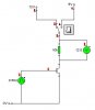
I have a circuit, with a resistor between the drain and 12V, of a mosfet and I have a wave, switching the mosfet on and off. During the off periods, the resistor gets no power. I was wondering if it's possible to make it, so that when the mosfet is on, the resistor has 12V, and when off, it has 5V. Can this be done? Or should I be looking at different components?
-Peter