Continue to Site

Welcome to our site!

Electro Tech is an online community (with over 170,000 members) who enjoy talking about and building electronic circuits, projects and gadgets. To participate you need to register. Registration is free. Click here to register now.

  • Welcome to our site! Electro Tech is an online community (with over 170,000 members) who enjoy talking about and building electronic circuits, projects and gadgets. To participate you need to register. Registration is free. Click here to register now.

MOSFET Single Pulse Generator

Status
Not open for further replies.

abbarue

New Member
@All
I need a simple pulse generator that can fire 10 MOSFETs connected in Parallel.
I want it to only put out one pulse and then shut off.
Like the circuits used to crush pop cans and shrink coins.
I haven't found a schematic for one on any of those websites that do that.
I'm looking for a pulse in the range of 1mS to 10mS.

I'm surprised how hard it is to find something so simple.
All the circuits I have found are designed to generate a continuous pulse train.
I need one that only does one pulse and shuts the MOSFETS off.
And keeps them off until the next time I fire it.

I have a hundred buz11's so I would like to use those.
Also have lots of 555s, quad op amps and hex inverters.

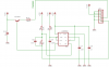
I build the "Variable Pulse Width Oscillator" circuit from this website:
LM555 Timer Circuits
Maybe someone has a mod for this circuit that will do the job.

Also every time I connect the power to the buz11 it conduct.
How do I keep it turned off until I want it on?

I'm not used to using MOSFETS yet, only regular power transistors.
The fact that they stay on until turned off can be a nuisance.

Thanks in advance Harold.
 
hi,
A 555 configured as a Monostable will give a single pulse of defined width every time you push a button.
Look at the 555 datasheet for the Monostable.

You may require a current buffer between the output of the 555 and the 10 MOS gates.
This is to ensure a very fast turn ON, which I think you are asking for.
 
Last edited:
you should be able to expect less than 5uS switching time with a 200mA 555 output. That would be a problem in a power converter but you are only switching it once in a while.

BTW, that tendency to "stay on" is a mixed blessing. it is the cause of the both the low power drive capability (try putting 100A through a bipolar with out a heatsink) and the static sensitivity (though some FETs have built in gate source zeners these days that helps with that).
 
If you are making some sort of pulse device, have you considered a large inductrial SCR or mosfet like this.

The one shown is expensive, as it is new. I got three, large SCRs (pulse current 1500A or so) for about $10 on ebay awhile back. I used the 555-based trigger circuit, attached. John
 

Attachments

  • ls6665-1.jpg
    ls6665-1.jpg
    59.9 KB · Views: 1,359
  • trigger.png
    trigger.png
    23.9 KB · Views: 1,677
Thanks for the quick reply.
I found the ideal circuit I was looking for.
Here is the link:
https://www.overunity.com/index.php?action=dlattach;topic=1310.0;attach=23885
Here is the link to what I wanted it for:
https://www.overunity.com/index.php/topic,1310.640.html

The problem with the 555 timer circuit is; if the pushbutton is held down it keeps sending pulses.
So one has to let the pushbutton go fast enough so this won't happen.
The link I sent shows a single fire pulse circuit that won't send any more pulses until the
pushbutton is released so the cap C1 can recharge again.
Also the pushbutton can be replaced by an NPN tansistor pulsed by a 555, to get a pulse train.
The 555 controls the frequency of the pulses, and "C1" controls the pulse width.
Very cheap PWM, less then $2 in parts, for anyone interested.
 
Last edited:
The problem with the 555 timer circuit is; if the pushbutton is held down it keeps sending pulses.
So one has to let the pushbutton go fast enough so this won't happen.

Actually that is not the case. The circuit I posted, which is simply an implementation of the monostable suggested by ericgibbs, gives only one pulse. Moreover, it does not give a secondary pulse when the switch is released.

The link to over-unity is amusing. I love this opening statement:
link said:
Dudes, it seems the thread is getting increasingly vague.

Please keep us updated on your success.

John
 
@jpanhalt
I rechecked the circuit and I found a component wasn't properly connected.
It works great now.
Thanks for the help, and I will keep you posted on my progress.
The following website shows a successful replication of the device I'm working on.
With plenty of measurement data.

**broken link removed**

I hope to get similar results.
Later, Harold.
 
Last edited:
A question about MOSFETS:
A mosfet is connected to a capacitor bank that has a higher voltage stored in it,
then the voltage rating of the mosfet. and the mosfet is in the off position.
Will the mosfet break down?
I understand that it can't switch a higher voltage then it is rated for.
I just don't know if it can keep a circuit turned off that has a higher voltage.

The reason for asking.
If I happen to overcharge a capacitor bank that is to be switched by a mosfet,
would I have a chance to bleed off the extra voltage before I switch it?
 
Last edited:
it will break down... how are you charging the bank? If it is a slow charge then an avalanche rated FET might be all you need since the FET will limit the voltage on the caps as long as it has he heat sinking to act as a linear regulator.

Otherwise you need to prevent the voltage from getting there either by additional circuitry or by getting a FET capable of withstanding the highest voltage you ever expect to see.
 
I am sorry to revive this old thread, I hope it is okay though...

I have a question to post #5 and the single pulse circut he refers to.

Thanks for the quick reply.
I found the ideal circuit I was looking for.
Here is the link:
Free Energy Alternative ZeroPoint Green Tesla Power Open Source Research Forum OverUnity.com - a...0

Will it be possible to feed the Q1-Q2-Q3 circut with 5 volts instead of 10V? And will I be able to get approx 2 seconds of pulse length with this circut? I am planning on using BC847 by the way and I want to turn on a FET just like the diagram is showing.

I tried simulating it in EWB but I find the results misleading meaning that the pulse length seems to be very short. Increasing the capsitor value just seems to stall the simulation.

I'll appreciate any information you might be able to add.

Best regards
 
Status
Not open for further replies.

Latest threads

Back
Top