Continue to Site

Welcome to our site!

Electro Tech is an online community (with over 170,000 members) who enjoy talking about and building electronic circuits, projects and gadgets. To participate you need to register. Registration is free. Click here to register now.

  • Welcome to our site! Electro Tech is an online community (with over 170,000 members) who enjoy talking about and building electronic circuits, projects and gadgets. To participate you need to register. Registration is free. Click here to register now.

MOSFET Question

Status
Not open for further replies.

z9u2k

New Member
Hey,

I'm a bit confused.

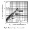
I have an IRF5305 P-Channel MOSFET from International Rectifier.

According to the datasheet (graph attached), at -Vds = -Vgs = 5V, I should get a drain-to-source current of at least -5A - but this is not the case.

As a test, I connected the MOSFET as follows:
- Gate -> Ground
- Source -> +5V
- Drain -> Ground, through an 0.1Ω resistor.

(yes - I know this is a bit unsafe - I have overcurrent protection in my PSU)

I'm using a 500W PC PSU, which is capable of supplying significant current at 5V, so this is not the bottleneck.

When I measure the voltage across the resistor, I get an initial reading of about 70mV, and the reading keeps climbing at a rate of about 1mV every 1.5 second - which indicates a current much lower than the current in the datasheet. Measuring the current directly yields the same result.

What am I missing?

Thanks!
 

Attachments

  • IRF5305.jpg
    IRF5305.jpg
    126.7 KB · Views: 174
Bad Fet, or your supply is not at 5V.
 
If the MOSFET starts out OK, it may die very soon. It may be dissipating 30 or 40 Watts, which will kill it in short order unless you have a big heatsink. Note that the datasheet says that the test is done for 20 microseconds.
 
Last edited:
So, this is not a continues current - but a peak current, and since the die heats due to the power dissipated - the current rating degrades...

Have I got it right?

Anyways, if that's the case, I couldn't find in the datasheet the Rds(on) as a function of the gate voltage - how can I estimate the max. current under a certain gate voltage that will not kill the MOSFET?

Thanks!
 
What kills the MosFet is the power dissipation or Vds voltage. If you fully turn it on, the FET dissipates almost no power. If it is off, it doesn't dissipate any power. It only dissipates power if it is somewhere between fully on and fully off. You have to turn it on/off as fast as possible, to minimize the time it is in the region where it is dissipating power.
 
You should use a logic level moosfet for this application. The IRF5305 is meant for -10V at the gate, and will not be able to handle 5A at only 5V.

Also, with the gate and drain at only 5V, you're entering the saturation region, which is limiting your current. You need to be at the top of the slop on the graphs where it just starts leveling out. Not in the flat region.
 
I would probably use a 12V power supply then... :)

But still, for next time, how can I know in advance the amount of current to expect under certain conditions?
 
The graph in the datasheet is for a "typical" Mosfet. Your Mosfet might have spec's that are lower than typical but still passing.

Look at the text in the datasheet for the minimum guaranteed spec's.
 
Look at the supplied curves, guys. According to the graph, at -5V Source to Gate, and -5v Drain to Source, Current should be ~5A. Using R = Vdrain) / I(drain), the FET has 1 ohm resistance. All that can be expected across the 0.1 ohm resistor is 9% of 5V.

It should get hot quickly at ~25 watts. I bet the voltage dropping with time across the resistor is due to the out of range heat building up.

I bet you could brand your thumb with the imprint of a MOSFET if you squeezed it to check if it's hot.:eek:
 
Last edited:
Look at the supplied curves, guys. According to the graph, at -5V Source to Gate, and -5v Drain to Source, Current should be ~5A. Using R = Vdrain) / I(drain), the FET has 1 ohm resistance. All that can be expected across the 0.1 ohm resistor is 9% of 5V.

It should get hot quickly at ~25 watts. I bet the voltage dropping with time across the resistor is due to the out of range heat building up.

I bet you could brand your thumb with the imprint of a MOSFET if you squeezed it to check if it's hot.:eek:
Yeah, that was my point.
 
I bet you could brand your thumb with the imprint of a MOSFET if you squeezed it to check if it's hot.:eek:

Indiana Jones and the Raiders of the Lost Ark style? :)

Anyways - thanks! As I said, I'll just switch to a 12V supply and use an LM7805 to power everything but the MOSFET and the MOSFET driver... Since this is a closed loop buck SMPS, there shouldn't be a problem feeding the inductor 12V instead of 5V...

I was thinking of using a MAX626 as the driver, since it accepts 12V as Vdd, has logic-level input and can supply a peak of 2A (which should be quite enough for a gate charge of 63nC at about 500kHz).
 
Last edited:
Don't forget that the graph in the original post is for a junction temperature of 25°C. If the FET is "hot", you have to look at the Rds on vs temp graph as well.

What are the particulars of your buck converter... Vin, Vout, Iout, PWM etc.???
 
Buck converter is also a high side switch, so you will have to add a bootstrap circuit to the mosfet driver to keep the Vgs voltage above 10V.
 
Buck converter is also a high side switch, so you will have to add a bootstrap circuit to the mosfet driver to keep the Vgs voltage above 10V.

Which is exactly why I chose a p-channel MOSFET - so I'll I have to do it to pull to ground (source is at 12V).

What are the particulars of your buck converter... Vin, Vout, Iout, PWM etc.???

That's a constant-current PSU for a single cell NiMH charger.

This is an educational purpose project - so I'm using discreet components where I can.

My PWM "controller" is a just simple comparator with a LPF, much like in Microchip's AN874.

Vin = 12V
Vout = Whatever it takes to get a certain current (around 2-3 volts)
PWM = 400-500kHz
Iout (max) = 2A

Reference voltage is generated using PIC's PWM with a LPF. Voltage over sense resistor is fed back to the PIC (as well as the comparator), which controls the charge algorithm.
 
Sorry, forgot you're using a PFET. Something I should try one of these days. :p
 
Last edited:
Status
Not open for further replies.

Latest threads

New Articles From Microcontroller Tips

Back
Top