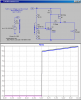
The arrow as shown is for a "P" channel. The arrow would point towards the gate if were a "N" channel.
**broken link removed**
No. For a PFET, the diode cathode is always closest to the source lead! The diode symbol should always be reversed biased. For the correct placement of a PFET in the OP's circuit, the diode cathode should be in the lead closest to the + supply terminal AND the diode should point toward the + supply terminal!
Last edited: