Continue to Site

Welcome to our site!

Electro Tech is an online community (with over 170,000 members) who enjoy talking about and building electronic circuits, projects and gadgets. To participate you need to register. Registration is free. Click here to register now.

  • Welcome to our site! Electro Tech is an online community (with over 170,000 members) who enjoy talking about and building electronic circuits, projects and gadgets. To participate you need to register. Registration is free. Click here to register now.

Mosfet Gate Capacitor?

Status
Not open for further replies.
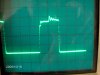
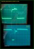
Have noticed when putting a 20pf scope probe on the gate to a sfp9540 mosfet, that some oscillation is damped out when full turn on is reached. There is 22ohm gate resistor, and is being driven by an inverting TC4426 mosfet driver. Is it worth putting a 20pf cap on the gate to clean up the waveform? Would the other side of the cap go to gnd?

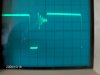
Follow up question, there is a bit of oscillation encountered at turn off too. Any reason to go after that, and how? A 47k pulldown resistor is used on the MCP4426 inverting input.
 
Just leave the scope probe attached :)

Just kidding. It would be helpful if you posted a schematic, so we can see what you're working on.
 
It is a continuing experiment with a solar battery charge controller. Playing with a buck converter configuration at the moment. Please note the irfr5305 has been replaced with the sfp9540, as the irfr5305 seemed a little too touchy for my bumbling around.

P.S. Schematic doesn't show pull down resistor on TC4426 input, but its there.
 

Attachments

  • smps_schem2.jpg
    smps_schem2.jpg
    49.7 KB · Views: 1,265
Last edited:
I'm wondering if you've formed a closed-loop margnially stable oscillator between your MOSFET and the driver power connection. If so, then bypassing capacitors and careful layout might fix the problem.
 
Last edited:
The loop is not closed yet, just straight pwm at whatever volts, amps the circuit allows. The lamp load is 500-600ma in full sun. Its a really crummy, cloudy day out, and the circuit is not even stable enough to test under load yet.

Was hoping to work on the feedback loop today.
 
Sorry, talking about the wrong oscillating loop. Will stick on a 20pf bypass to gate and take another look at the waveform. The driver and mosfet are on vero board, could that be the problem?
 
My guess it's caused by coupling from your transistor back to it's driver. When the transistor switches, it draws current through the resistance and inductance of the wires and voltage source resistence, which couples back to the driver. Use seperate connections for your switch and driver back to your voltage source. Try larger guage wire, and bypass caps. You many also increase the value of your 150UF smoothing cap. Your voltage source resistance might bite you, and require a redesign.

But if using a small cap on the gate works, then go with it.
 
Last edited:
Hi there,


Oscillation problems like this often occur because of the small inductance in series with
the source lead. The inductance works with the miller capacitance to cause turn on
turn off, turn on, turn off, etc., until the device finally turns on or off compeletely.
Any extra lead length there only makes the problem worse.
The cure is to shorten the source lead as much as possible. When that doesnt work,
making the gate resistor a higher value has almost the same effect as more
capacitance, but both cause slower switching times so the device has to be checked
for higher switching losses.
Also to check is the bypass cap for the driver chip. If the driver chip doesnt have any
now would be a good time to add one cap across the power supply pins. If the
chip cant get the required power fast enough it wont be able to drive the MOSFET
properly.

I almost forgot to mention:
Sometimes lowering the drive resistance helps instead of increasing it.

Hey, i noticed you didnt show the power supply voltage there?
 
Last edited:
Oscillations also appear to happen when the scope lead isn't properly grounded.

I lost count of the supposedly experienced engineers that I had to teach how to take high speed measurements.
 
1) Yes I was taking the driver supply from the pfet source. Re-routed as seperate supply line. Driver gnd is direct wire to supply gnd.

2) Mosfet driver is bypassed with 1.5uf tantalum cap.

3) Oscilloscope probe is grounded to supply gnd.

4) Solar panel voltage is around 20.4V in full sun.

5) Source and Drain to pfet is about 3" (each leg) of 16 gauge wire.

6) Gate wire and trace about equal length for about 1" total.

Happy to show my ignorance here, so included the waveform pics. First picture is taken right at the mosfet gate. Adding the 20pf cap did nothing really. Second pic is at the pfet drain. I was confused when looking at the output side of the pfet drain, and sort of transposed that to the gate. It may actually have nothing to do with the gate, but more of a function of the circuit?

Just learning about buck converter, so if someone could comment on cause and effects of the two waveforms, would be much appreciated.

Thanks to everyone for the help thus far.

Trace Notes: Vert 5V/div Horiz 5us/div
 

Attachments

  • IM000254.JPG
    IM000254.JPG
    1 MB · Views: 501
  • IM000258.JPG
    IM000258.JPG
    809.4 KB · Views: 552
Hi,

Oh ok, that oscillation isnt always a problem. As long as the ringing peak doesnt
go too high. That's caused mostly by the resonance between the diode capacitance
and the output inductance.

Here are the two waveforms annotated a bit...you might have to zoom in to
see the annotations though.
 

Attachments

  • IM302.jpg
    IM302.jpg
    203.5 KB · Views: 539
Last edited:
I'm happy that you showed the waveforms. They don't look like scope artifacts, so that's cleared up.

I haven't done the calculation, but you should confirm that 33µH is correct. To me it seems pretty small for a 30 kHz switcher. It also could be saturating. You should also confirm that it's rated for the current you're passing through it. Do you have a part number or markings?
 
Last edited:
Keep in mind that solar panel is a current source clamped by forward biased diodes.

You can make it look like a short period voltage source with a big enough cap. Don't know what current you are pulling during coil charge but 150 uF may not be large enough.

Does ringing go away if powered from a real voltage source power supply?
 
MrAl:
Thanks for the annotations, really helps.

Meneary:
The inductor is a high current model Bourns.The inductor was mostly chosen for the highest inductance at that amp capability.

The lamp load is only 500-600ma, which will be replaced by a 12 deep cycle battery only when things get ironed out. The solar panel is rated at 17V, 4.4A under ideal conditions.

Bumped the switcher back to 100khz and the gate waveform now has a flat top....yeah:)! Had been vacillating back and forth on just what frequency to use. The drain waveform spends much less time oscillating, although the peaks look a little higher.

I would post the waveforms, but it looks like the old digital camera has decided to give up the ghost:mad:, new batteries, still no good.

RCinFLA:
I'm back on bench supply power now because the sun is fading now. At 34khz, and bench supply, still had the oscillations on the gate drive. Moved up to the 100khz and nice flat top now. On the bench supply there is 500ma being pulled for the lamp, not sure if that answers the coil charge question.

Will be picking up some more low ESR caps soon, so could experiment with larger/smaller input cap.
 
It could still be artifact from your scope's gournd wire, depending on how long that wire is. Either way, it doesn't look like a big deal to me.
 
Hi,

That ringing is the diodes capacitance in series with the 33uH inductor.
This is very very typical for a buck, and i've seen it many times in the past.
If you add more capacitance (a little more) across the diode, you see the
frequency of the ringing go lower, and if you calculate the resonate frequency
lo and behold it's the same as the ringing :)
It happens because the diode stops conducting, and once it stops conducting
it's like an open circuit and all that is left is the capacitance in series with the
inductor. The mosfets capacitance may contribute a little too during that time.
It's not too bad as long as it doesnt go too high and thus exceed some components
voltage rating.

I almost forgot to comment on the inductor value itself...
33uH does sound quite low for 30kHz so it is good that the frequency was increased to
100kHz. The lower inductor value as well as possibly saturating too soon
also puts a strain on the output capacitor, and the
output capacitor needs to be able to handle the rms ripple current without any problem.
At 100kHz that situation gets better too.
 
Last edited:
You are going to need a good low Rs cap of about 1000 uF on output to get to your full power goal. That's at 100 KHz switching speed.

At your final power target, coil inductance is too high for even 30 Khz operation. At 30 KHz should use about 15 uH, at 100 kHz use about 5 uH.

Peak coil current is going to be upwards of 6-8 amps. It's more difficult to keep core out of saturation at larger inductance value. You can use larger inductance but the coil core size is going to get a lot bigger.

Input capacitor should handle supplying 4-5 amps for 75% of period. At 30 kHz this would be about 800-1000 uF. At 100 kHz would be 250-500 uF.

If your going to hunt for maximum power point on panel you need to keep ripple voltage on panel to minimum otherwise it will fake out your search.

Remember panel should get constant current load. Input cap has to supply the additional coil peak current otherwise panel voltage drops out.

Also need a backwash switch or diode when panel illumination drops out.
 
Last edited:
Here is couple of candidates for both input 470uf and 1000uf output caps from Rubycon. May substitute a general purpose 105C cap for output and swap the current output over to the input, until order arrives.

Here is a couple of inductor candidates. J.W. Miller 5uf and 10uf. The previously mentioned 33uf is pretty beefy, and not sure if it would saturate or not, seemed to be pretty conservative. How I would tell if coil is saturating or not? Still hunting for the sweet spot, i.e. frequency vs. inductor value, but willing to try a few combos. Before this conversation, I was actually was thinking of trying to raise the inductor value, and lower the frequency to lessen switching losses. Those type of inductors start getting expensive though.

The output voltage a-d was worked out in the microcontroller section. It can be sampled every 4th, 8th pwm (rising edge) interrupt to give consistent results. There is an Alleggro hall effect sensor for measuring current. So mppt will be looked at in the future. The hall effect output needs to be buffered though, because a direct connect to the micro a-d seems to suck the life out of sensor.

I was going to try and set the control loop up as a constant voltage device for the battery, and drop the converter out if panel current goes below a set minimum. In low light situations have seen the voltage collapse, I know this will be a problem, and need to come to grips with.

Yes there is a blocking diode on the input after the fuse and on/off switch. I need to update the schematic to show what all is involved.

Scope probe is Tek 6105A 10x.
 
Hi again,


The site for the 1000uf cap was doing maintenance so i couldnt look at that cap yet.
The inductor however you are right is pretty beefy. As i said before though, the
inductor saturation is not the only issue here. The other is the ripple current rating
of the output cap(s). Using one cap, a 30uH inductor, a 21v supply, 12v output,
the cap ripple peak to peak current can be calculated:
Ipp=v*dt/L
where dt approximately comes out to 12us for a 50kHz frequency, so we get
Ipp=3.6 amps peak to peak, or 1.8 amps peak or 1.04 amps rms, so the cap
would have to be able to handle that ripple current. If the battery voltage
drops down a little the ripple will go up a little, and also with current due
to the resistive and other losses in the circuit.
With 30kHz that ripple current will go up to about 1.65 amps rms.
With 100kHz that ripple current will go down to about 0.5 amps rms.
That shows the effect of the frequency on the ripple current and thus the required
ripple current rating of the capacitor.
The voltage rating of the capacitor is usually recommended to be 1.5 times the output
voltage, so the cap should have a voltage rating of at least 18v, but i have seen
16v caps on well regulated power supplies. Even better would be 25v of course.

How many amps do you expect to output to the battery in the
final design? We need this info in order to determine if your inductor will saturate
or not for a given frequency and value. If you only need to push 4 amps out,
that inductor should be able to handle that as the max current will be up around
6.4 amps during turn on surge and slightly less than 6 amps during normal operation.
That leaves plenty of headway too which is certainly a good thing.
You'll also need to implement current limit somehow if you havent already done that.

Also, what kind of ripple voltage are you looking for? The cap ESR has a very big effect
on this specification, although a workaround is to use a post filter with a small inductance
(even air core hand wound) and a second capacitor but not in the feedback path.
You can get super smooth output that way for little extra cost and less headaches after
some normal capacitor aging.

Lastly, how does the AD converter "suck the life out of" the hall effect sensor?
What is the symptom when this happens?
 
Last edited:
.... At your final power target, coil inductance is too high for even 30 Khz operation. At 30 KHz should use about 15 uH, at 100 kHz use about 5 uH.
I disagree. In a continuous buck converter, the first indication that the inductor is too small for the operating frequency is when you see the diode stop conducting!

33kHz is unusually slow for a switcher these days, so I dug out the design guide for the (50kHz) LM5576. For 20-25V in, 12V out, 1A they recommend 470 to 680µH. Lower currents need even more inductance. 5µH is too small unless you can guarantee currents of 20A or more. Simulation should confirm this. Maybe tomorrow unless someone else wants to do it.

@nickelflippr, the easiest solution appears to be: keep your frequency high. Those low ESR capacitors will also help.
 
Status
Not open for further replies.

Latest threads

New Articles From Microcontroller Tips

Back
Top