Electro Tech is an online community (with over 170,000 members) who enjoy talking about and building electronic circuits, projects and gadgets. To participate you need to register. Registration is free. Click here to register now.
Welcome to our site! Electro Tech is an online community (with over 170,000 members) who enjoy talking about and building electronic circuits, projects and gadgets. To participate you need to register. Registration is free. Click here to register now.
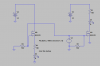
I have a mosfet trying to drive an LED. I have 2 different configuration as shown.
Why isn't the current through the resistor the same when connections are interchanged.
hi,
Consider the actual Vgs voltage in the two cases.
In the M1 case the full V1 appears across the Gate to Source junction.
In the M2 case Vgs is reduced from V1 by the voltage drop across the Source resistor and LED.
E
This site uses cookies to help personalise content, tailor your experience and to keep you logged in if you register.
By continuing to use this site, you are consenting to our use of cookies.